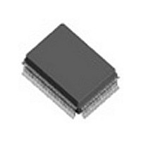
IDT82V2108PXG IDT, Integrated Device Technology Inc, IDT82V2108PXG Datasheet - Page 239

IDT82V2108PXG
Manufacturer Part Number
IDT82V2108PXG
Description
IC FRAMER T1/J1/E1 8CH 128-PQFP
Manufacturer
IDT, Integrated Device Technology Inc
Datasheet
1.IDT82V2108PX8.pdf
(292 pages)
Specifications of IDT82V2108PXG
Controller Type
T1/E1/J1 Framer
Interface
Parallel
Voltage - Supply
2.97 V ~ 3.63 V
Current - Supply
160mA
Operating Temperature
-40°C ~ 85°C
Mounting Type
Surface Mount
Package / Case
128-MQFP, 128-PQFP
Screening Level
Industrial
Mounting
Surface Mount
Operating Temperature (min)
-40C
Operating Temperature (max)
85C
Lead Free Status / RoHS Status
Lead free / RoHS Compliant
Other names
82V2108PXG
Available stocks
Company
Part Number
Manufacturer
Quantity
Price
Company:
Part Number:
IDT82V2108PXG
Manufacturer:
IDT, Integrated Device Technology Inc
Quantity:
10 000
Part Number:
IDT82V2108PXG
Manufacturer:
IDT
Quantity:
20 000
Company:
Part Number:
IDT82V2108PXG8
Manufacturer:
IDT, Integrated Device Technology Inc
Quantity:
10 000
- Current page: 239 of 292
- Download datasheet (3Mb)
IDT82V2108
T1 / J1 RBOM Enable (02AH, 0AAH, 12AH, 1AAH, 22AH, 2AAH, 32AH, 3AAH)
IDLE:
AVC:
Yellow signal in T1/J1 ESF format.
BOCE:
T1 / J1 RBOM Code Status (02BH, 0ABH, 12BH, 1ABH, 22BH, 2ABH, 32BH, 3ABH)
IDLEI:
BOCI:
BOC[5:0]:
Programming Information
Bit Name
Bit Name
Default
Default
Bit No.
Bit No.
Type
= 0: Disable the interrupt on the INT pin when there is a transition from BOM to non-BOM in the received data stream.
= 1: Enable the interrupt on the INT pin when there is a transition from BOM to non-BOM in the received data stream.
This bit selects the validation criteria used to acknowledge the Bit Oriented Message (BOM) in the received data stream, or to acknowledge the
= 0: The BOM or the Yellow signal is acknowledged when the pattern is matched and the received code is identical 8 out of 10 times.
= 1: The BOM or the Yellow signal is acknowledged when the pattern is matched and the received code is identical 4 out of 5 times.
= 0: Disable the interrupt on the INT pin when a valid BOM code is detected in the received data stream.
= 1: Enable the interrupt on the INT pin when a valid BOM code is detected in the received data stream.
= 0: No transition from Bit Oriented Message (BOM) to non-BOM in the received data stream.
= 1: A transition from BOM to non-BOM in the received data stream.
This bit is cleared to ‘0’ after the register is read.
= 0: No Bit Oriented Message (BOM) is detected.
= 1: BOM is detected in the received data stream.
This bit is cleared to ‘0’ after the register is read.
These bits directly reflect the content of the Bit Oriented Message (BOM) in the received data stream.
All ‘One’s in the BOC[5:0] mean there is no BOM received.
The BOC[5] corresponds to the MSB of the code while the BOC[0] corresponds to the LSB.
Type
IDLEI
7
0
R
7
BOCI
R
6
0
6
BOC[5]
Reserved
R
5
1
5
BOC[4]
R
4
1
4
229
BOC[3]
R
3
1
3
BOC[2]
IDLE
R/W
R
2
1
2
0
T1 / E1 / J1 OCTAL FRAMER
BOC[1]
AVC
R/W
1
0
R
1
1
March 5, 2009
BOC[0]
BOCE
R/W
0
0
R
0
1
Related parts for IDT82V2108PXG
Image
Part Number
Description
Manufacturer
Datasheet
Request
R

Part Number:
Description:
TRANSLATION DEVICE DPI 80-PQFP
Manufacturer:
IDT, Integrated Device Technology Inc
Datasheet:

Part Number:
Description:
IDT PART
Manufacturer:
IDT, Integrated Device Technology Inc
Datasheet:

Part Number:
Description:
IC LIU T1/E1/J1 OCTAL 256PBGA
Manufacturer:
IDT, Integrated Device Technology Inc
Datasheet:

Part Number:
Description:
IC FREQ TIMING GENERATOR 28TSSOP
Manufacturer:
IDT, Integrated Device Technology Inc
Datasheet:

Part Number:
Description:
IC CLK DVR PLL 1:10 40VFQFPN
Manufacturer:
IDT, Integrated Device Technology Inc
Datasheet:

Part Number:
Description:
IC CLK FANOUT BUFFER 1:18 32LQFP
Manufacturer:
IDT, Integrated Device Technology Inc
Datasheet:

Part Number:
Description:
IC CLK FANOUT BUFFER 1:18 32LQFP
Manufacturer:
IDT, Integrated Device Technology Inc
Datasheet:

Part Number:
Description:
IC CK505 VREG/RES 56TSSOP
Manufacturer:
IDT, Integrated Device Technology Inc
Datasheet:

Part Number:
Description:
IC SDRAM CLK DVR 1:10 48-TSSOP
Manufacturer:
IDT, Integrated Device Technology Inc
Datasheet:

Part Number:
Description:
IC CLK DVR PLL 1:10 48TSSOP
Manufacturer:
IDT, Integrated Device Technology Inc
Datasheet:

Part Number:
Description:
IC FLEXPC CLK PROGR P4 56-TSSOP
Manufacturer:
IDT, Integrated Device Technology Inc
Datasheet:

Part Number:
Description:
IC FLEXPC CLK PROGR P4 56-TSSOP
Manufacturer:
IDT, Integrated Device Technology Inc
Datasheet:

Part Number:
Description:
IC FLEXPC CLK PROGR P4 56-SSOP
Manufacturer:
IDT, Integrated Device Technology Inc
Datasheet:

Part Number:
Description:
IC PLL CLK DRIVER 2.5V 28-TSSOP
Manufacturer:
IDT, Integrated Device Technology Inc
Datasheet:

Part Number:
Description:
IC CLOCK DRIVER 2.5V 24-TSSOP
Manufacturer:
IDT, Integrated Device Technology Inc
Datasheet:


