C8051F120DK Silicon Laboratories Inc, C8051F120DK Datasheet - Page 179
C8051F120DK
Manufacturer Part Number
C8051F120DK
Description
DEVKIT-F120/21/22/23/24/25/26/27
Manufacturer
Silicon Laboratories Inc
Type
MCUr
Datasheet
1.C8051F120DK.pdf
(350 pages)
Specifications of C8051F120DK
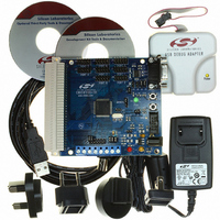
Contents
Evaluation Board, Power Supply, USB Cables, Adapter and Documentation
Processor To Be Evaluated
C8051F12x and C8051F13x
Interface Type
USB
Silicon Manufacturer
Silicon Labs
Core Architecture
8051
Silicon Core Number
C8051F120
Silicon Family Name
C8051F12x
Lead Free Status / RoHS Status
Contains lead / RoHS non-compliant
For Use With/related Products
C8051F120, 121, 122, 123, 124, 125, 126, 127
Lead Free Status / Rohs Status
Lead free / RoHS Compliant
Other names
336-1224
Available stocks
Company
Part Number
Manufacturer
Quantity
Price
Company:

Part Number:
C8051F120DK
Manufacturer:
SiliconL
Quantity:
4


C8051F120/1/2/3/4/5/6/7
C8051F130/1/2/3
13.3. External Reset
The external RST pin provides a means for external circuitry to force the MCU into a reset state. Asserting
the RST pin low will cause the MCU to enter the reset state. It may be desirable to provide an external pul-
lup and/or decoupling of the RST pin to avoid erroneous noise-induced resets. The MCU will remain in
reset until at least 12 clock cycles after the active-low RST signal is removed. The PINRSF flag (RST-
SRC.0) is set on exit from an external reset.
13.4. Missing Clock Detector Reset
The Missing Clock Detector is essentially a one-shot circuit that is triggered by the MCU system clock. If
the system clock goes away for more than 100 µs, the one-shot will time out and generate a reset. After a
Missing Clock Detector reset, the MCDRSF flag (RSTSRC.2) will be set, signifying the MSD as the reset
source; otherwise, this bit reads ‘0’. The state of the RST pin is unaffected by this reset. Setting the
MCDRSF bit, RSTSRC.2 (see Section “
14. Oscillators
” on page
185
) enables the Missing Clock Detector.
13.5. Comparator0 Reset
Comparator0 can be configured as a reset input by writing a ‘1’ to the C0RSEF flag (RSTSRC.5).
Comparator0 should be enabled using CPT0CN.7 (see Section “
10. Comparators
” on page
119
) prior to
writing to C0RSEF to prevent any turn-on chatter on the output from generating an unwanted reset. The
Comparator0 reset is active-low: if the non-inverting input voltage (CP0+ pin) is less than the inverting
input voltage (CP0- pin), the MCU is put into the reset state. After a Comparator0 Reset, the C0RSEF flag
(RSTSRC.5) will read ‘1’ signifying Comparator0 as the reset source; otherwise, this bit reads ‘0’. The state
of the RST pin is unaffected by this reset.
13.6. External CNVSTR0 Pin Reset
The external CNVSTR0 signal can be configured as a reset input by writing a ‘1’ to the CNVRSEF flag
(RSTSRC.6). The CNVSTR0 signal can appear on any of the P0, P1, P2 or P3 I/O pins as described in
Section “
18.1. Ports 0 through 3 and the Priority Crossbar Decoder
” on page
238
. Note that the Cross-
bar must be configured for the CNVSTR0 signal to be routed to the appropriate Port I/O. The Crossbar
should be configured and enabled before the CNVRSEF is set. When configured as a reset, CNVSTR0 is
active-low and level sensitive. CNVSTR0 cannot be used to start ADC0 conversions when it is configured
as a reset source. After a CNVSTR0 reset, the CNVRSEF flag (RSTSRC.6) will read ‘1’ signifying
CNVSTR0 as the reset source; otherwise, this bit reads ‘0’. The state of the ⁄RST pin is unaffected by this
reset.
13.7. Watchdog Timer Reset
The MCU includes a programmable Watchdog Timer (WDT) running off the system clock. A WDT overflow
will force the MCU into the reset state. To prevent the reset, the WDT must be restarted by application soft-
ware before overflow. If the system experiences a software or hardware malfunction preventing the soft-
ware from restarting the WDT, the WDT will overflow and cause a reset. This should prevent the system
from running out of control.
Following a reset the WDT is automatically enabled and running with the default maximum time interval. If
desired the WDT can be disabled by system software or locked on to prevent accidental disabling. Once
locked, the WDT cannot be disabled until the next system reset. The state of the RST pin is unaffected by
this reset.
The WDT consists of a 21-bit timer running from the programmed system clock. The timer measures the
period between specific writes to its control register. If this period exceeds the programmed limit, a WDT
Rev. 1.4
179
Related parts for C8051F120DK
Image
Part Number
Description
Manufacturer
Datasheet
Request
R

Part Number:
Description:
SMD/C°/SINGLE-ENDED OUTPUT SILICON OSCILLATOR
Manufacturer:
Silicon Laboratories Inc
Part Number:
Description:
Manufacturer:
Silicon Laboratories Inc
Datasheet:
Part Number:
Description:
N/A N/A/SI4010 AES KEYFOB DEMO WITH LCD RX
Manufacturer:
Silicon Laboratories Inc
Datasheet:
Part Number:
Description:
N/A N/A/SI4010 SIMPLIFIED KEY FOB DEMO WITH LED RX
Manufacturer:
Silicon Laboratories Inc
Datasheet:
Part Number:
Description:
N/A/-40 TO 85 OC/EZLINK MODULE; F930/4432 HIGH BAND (REV E/B1)
Manufacturer:
Silicon Laboratories Inc
Part Number:
Description:
EZLink Module; F930/4432 Low Band (rev e/B1)
Manufacturer:
Silicon Laboratories Inc
Part Number:
Description:
I°/4460 10 DBM RADIO TEST CARD 434 MHZ
Manufacturer:
Silicon Laboratories Inc
Part Number:
Description:
I°/4461 14 DBM RADIO TEST CARD 868 MHZ
Manufacturer:
Silicon Laboratories Inc
Part Number:
Description:
I°/4463 20 DBM RFSWITCH RADIO TEST CARD 460 MHZ
Manufacturer:
Silicon Laboratories Inc
Part Number:
Description:
I°/4463 20 DBM RADIO TEST CARD 868 MHZ
Manufacturer:
Silicon Laboratories Inc
Part Number:
Description:
I°/4463 27 DBM RADIO TEST CARD 868 MHZ
Manufacturer:
Silicon Laboratories Inc
Part Number:
Description:
I°/4463 SKYWORKS 30 DBM RADIO TEST CARD 915 MHZ
Manufacturer:
Silicon Laboratories Inc
Part Number:
Description:
N/A N/A/-40 TO 85 OC/4463 RFMD 30 DBM RADIO TEST CARD 915 MHZ
Manufacturer:
Silicon Laboratories Inc
Part Number:
Description:
I°/4463 20 DBM RADIO TEST CARD 169 MHZ
Manufacturer:
Silicon Laboratories Inc