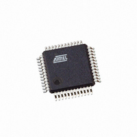
ATMEGA406-1AAU Atmel, ATMEGA406-1AAU Datasheet - Page 108

ATMEGA406-1AAU
Manufacturer Part Number
ATMEGA406-1AAU
Description
IC AVR MCU 40K 1MHZ 48LQFP
Manufacturer
Atmel
Series
AVR® ATmegar
Specifications of ATMEGA406-1AAU
Core Processor
AVR
Core Size
8-Bit
Speed
1MHz
Connectivity
I²C
Peripherals
POR, WDT
Number Of I /o
18
Program Memory Size
40KB (20K x 16)
Program Memory Type
FLASH
Eeprom Size
512 x 8
Ram Size
2K x 8
Voltage - Supply (vcc/vdd)
4 V ~ 25 V
Data Converters
A/D 10x12b
Oscillator Type
Internal
Operating Temperature
-30°C ~ 85°C
Package / Case
48-LQFP
Processor Series
ATMEGA48x
Core
AVR8
Data Bus Width
8 bit
Data Ram Size
2 KB
Interface Type
2-Wire
Maximum Clock Frequency
1 MHz
Number Of Programmable I/os
18
Number Of Timers
2
Maximum Operating Temperature
+ 85 C
Mounting Style
SMD/SMT
3rd Party Development Tools
EWAVR, EWAVR-BL
Development Tools By Supplier
ATAVRDRAGON, ATSTK500, ATSTK600, ATAVRISP2, ATAVRONEKIT
Minimum Operating Temperature
- 30 C
Cpu Family
ATmega
Device Core
AVR
Device Core Size
8b
Frequency (max)
1MHz
Total Internal Ram Size
2KB
# I/os (max)
18
Number Of Timers - General Purpose
2
Operating Supply Voltage (typ)
5/9/12/15/18/24V
Operating Supply Voltage (max)
25V
Operating Supply Voltage (min)
4V
On-chip Adc
10-chx12-bit
Instruction Set Architecture
RISC
Operating Temp Range
-30C to 85C
Operating Temperature Classification
Commercial
Mounting
Surface Mount
Pin Count
48
Package Type
LQFP
Controller Family/series
AVR MEGA
No. Of I/o's
18
Eeprom Memory Size
512Byte
Ram Memory Size
2KB
Cpu Speed
1MHz
Rohs Compliant
Yes
For Use With
770-1007 - ISP 4PORT ATMEL AVR MCU SPI/JTAG770-1005 - ISP 4PORT FOR ATMEL AVR MCU JTAG770-1004 - ISP 4PORT FOR ATMEL AVR MCU SPI
Lead Free Status / RoHS Status
Lead free / RoHS Compliant
Available stocks
Company
Part Number
Manufacturer
Quantity
Price
Part Number:
ATMEGA406-1AAU
Manufacturer:
AT
Quantity:
20 000
108
ATmega406
Figure 18-3. Accumulation Current Conversion
While the CC-ADC is converting, the CPU can enter sleep mode and wait for an interrupt from
the Accumulate Current conversion. After adding the new Accumulate Current value for Cou-
lomb Counting, the CPU can go back to sleep again. This reduces the CPU workload, and
allows more time spent in low power modes, reducing power consumption. The CC-ADC can
generate an interrupt if the result of an Instantaneous Current conversion is greater than a pro-
grammable threshold. This allows the detection of a Regular Current condition. This function is
available in Active mode and all sleep modes except Power-down and Power-off mode. This
allows an ultra-low power operation in Power-save, where the CC-ADC can be configured to
enter a Regular Current detection mode with a programmable current sampling interval. By set-
ting the CADSE bit in CADCSRA, the Coulomb Counter will repeatedly do one Instantaneous
Current conversion, before it is being turned off for a timing interval specified by the CADSI bits
in CADCSRA. This allows operating the Regular Current detection while keeping the Coulomb
Counter off most of the time.
The Coulomb Counter is halted in Power-down mode. In this mode, time measurements and the
battery self-discharge characteristics should be used to estimate the charge flow. When waking
up from Power-down mode, the CC-ADC will automatically resume continuous operation.
The CC-ADC is enabled by setting the CC-ADC Enable bit, CADEN, in CADCSRA. Note that the
bandgap voltage reference must be enabled separately, see
Register” on page
The CC-ADC will not consume power when CADEN is cleared. It is therefore recommended to
switch off the CC-ADC whenever the Coulomb Counter or Regular Current Detection functions
are not used. The CC-ADC is automatically disabled in Power-down and Power-off mode.
After the CC-ADC is enabled, either by setting the CADEN bit or leaving Power-down with
CADEN already set, the first four conversions do not contain useful data and should be ignored.
This also applies after clearing the CADSE bit.
In-system offset voltage for the CC-ADC is typically in the range 0 - 100 µV. To compensate for
this offset error, a CC-ADC offset value should be stored in EEPROM and subtracted from each
Accumulate Current conversions before the resulting value is added for Coloumb Counting. The
CC-ADC offset value can be found by performing a CC-ADC conversion at typical temperature
with zero current flowing through R
When the battery is not used or the current level stays very low for a long time, it is recom-
mended to estimate the charge flow instead of using the CC-ADC for Coloumb Counting. The
Accumulation Interrupt
Accumulation Data
Read byte 2
Read byte 1
Read byte 3
Read byte 4
Enable
123.
Setting of Digital Filters
SENSE
.
125, 250, 500,
or 1000 ms
DATA1
125, 250, 500,
or 1000 ms
DATA2
”BGCCR – Bandgap Calibration C
250, 500, 1000,
or 2000 ms
DATA 3
DATA5
2548E–AVR–07/06


