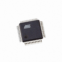
ATMEGA406-1AAU Atmel, ATMEGA406-1AAU Datasheet - Page 261

ATMEGA406-1AAU
Manufacturer Part Number
ATMEGA406-1AAU
Description
IC AVR MCU 40K 1MHZ 48LQFP
Manufacturer
Atmel
Series
AVR® ATmegar
Specifications of ATMEGA406-1AAU
Core Processor
AVR
Core Size
8-Bit
Speed
1MHz
Connectivity
I²C
Peripherals
POR, WDT
Number Of I /o
18
Program Memory Size
40KB (20K x 16)
Program Memory Type
FLASH
Eeprom Size
512 x 8
Ram Size
2K x 8
Voltage - Supply (vcc/vdd)
4 V ~ 25 V
Data Converters
A/D 10x12b
Oscillator Type
Internal
Operating Temperature
-30°C ~ 85°C
Package / Case
48-LQFP
Processor Series
ATMEGA48x
Core
AVR8
Data Bus Width
8 bit
Data Ram Size
2 KB
Interface Type
2-Wire
Maximum Clock Frequency
1 MHz
Number Of Programmable I/os
18
Number Of Timers
2
Maximum Operating Temperature
+ 85 C
Mounting Style
SMD/SMT
3rd Party Development Tools
EWAVR, EWAVR-BL
Development Tools By Supplier
ATAVRDRAGON, ATSTK500, ATSTK600, ATAVRISP2, ATAVRONEKIT
Minimum Operating Temperature
- 30 C
Cpu Family
ATmega
Device Core
AVR
Device Core Size
8b
Frequency (max)
1MHz
Total Internal Ram Size
2KB
# I/os (max)
18
Number Of Timers - General Purpose
2
Operating Supply Voltage (typ)
5/9/12/15/18/24V
Operating Supply Voltage (max)
25V
Operating Supply Voltage (min)
4V
On-chip Adc
10-chx12-bit
Instruction Set Architecture
RISC
Operating Temp Range
-30C to 85C
Operating Temperature Classification
Commercial
Mounting
Surface Mount
Pin Count
48
Package Type
LQFP
Controller Family/series
AVR MEGA
No. Of I/o's
18
Eeprom Memory Size
512Byte
Ram Memory Size
2KB
Cpu Speed
1MHz
Rohs Compliant
Yes
For Use With
770-1007 - ISP 4PORT ATMEL AVR MCU SPI/JTAG770-1005 - ISP 4PORT FOR ATMEL AVR MCU JTAG770-1004 - ISP 4PORT FOR ATMEL AVR MCU SPI
Lead Free Status / RoHS Status
Lead free / RoHS Compliant
Available stocks
Company
Part Number
Manufacturer
Quantity
Price
Part Number:
ATMEGA406-1AAU
Manufacturer:
AT
Quantity:
20 000
2548E–AVR–07/06
27 Boot Loader Support – Read-While-Write Self-Programming ......... 178
28 Memory Programming ......................................................................... 195
29 Operating Circuit .................................................................................. 223
30 Electrical Characteristics .................................................................... 225
31 Typical Characteristics – Preliminary ................................................ 232
32 Register Summary ............................................................................... 236
33 Instruction Set Summary .................................................................... 240
34 Ordering Information ........................................................................... 243
35 Packaging Information ........................................................................ 244
26.8 Using the JTAG Programming Capabilities ........................................................177
27.1 Boot Loader Features .........................................................................................178
27.2 Application and Boot Loader Flash Sections ......................................................178
27.3 Read-While-Write and No Read-While-Write Flash Sections .............................179
27.4 Boot Loader Lock Bits ........................................................................................181
27.5 Entering the Boot Loader Program .....................................................................183
27.6 Addressing the Flash During Self-Programming ................................................185
27.7 Self-Programming the Flash ...............................................................................186
28.1 Program And Data Memory Lock Bits ................................................................195
28.2 Fuse Bits ............................................................................................................196
28.3 Signature Bytes ..................................................................................................198
28.4 Calibration Bytes ................................................................................................198
28.5 Page Size ...........................................................................................................198
28.6 Parallel Programming .........................................................................................199
28.7 Programming via the JTAG Interface .................................................................211
30.1 Absolute Maximum Ratings* ..............................................................................225
30.2 DC Characteristics .............................................................................................225
30.3 General I/O Lines characteristics .......................................................................228
30.4 2-wire Serial Interface Characteristics ................................................................229
30.5 Reset Characteristics .........................................................................................230
30.6 Supply Current of I/O Modules ...........................................................................231
31.1 Pin Pull-up ..........................................................................................................232
31.2 Pin Driver Strength .............................................................................................233
31.3 Internal Oscillator Speed ....................................................................................234
ATmega406
v


