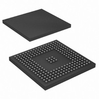
AT91SAM9XE512-CU Atmel, AT91SAM9XE512-CU Datasheet - Page 629

AT91SAM9XE512-CU
Manufacturer Part Number
AT91SAM9XE512-CU
Description
MCU ARM9 512K FLASH 217-BGA
Manufacturer
Atmel
Series
AT91SAMr
Datasheet
1.AT91SAM9XE128-QU.pdf
(860 pages)
Specifications of AT91SAM9XE512-CU
Core Processor
ARM9
Core Size
16/32-Bit
Speed
180MHz
Connectivity
EBI/EMI, Ethernet, I²C, MMC, SPI, SSC, UART/USART, USB
Peripherals
Brown-out Detect/Reset, POR, PWM, WDT
Number Of I /o
96
Program Memory Size
512KB (512K x 8)
Program Memory Type
FLASH
Ram Size
56K x 8
Voltage - Supply (vcc/vdd)
1.65 V ~ 1.95 V
Data Converters
A/D 4x10b
Oscillator Type
Internal
Operating Temperature
-40°C ~ 85°C
Package / Case
217-LFBGA
Package
217LFBGA
Device Core
ARM926EJ-S
Family Name
91S
Maximum Speed
180 MHz
Operating Supply Voltage
1.8|2.5|3.3 V
Data Bus Width
32 Bit
Number Of Programmable I/os
96
Interface Type
EBI/Ethernet/SPI/TWI/USART/USB
On-chip Adc
4-chx10-bit
Number Of Timers
6
Processor Series
AT91SAMx
Core
ARM926EJ-S
Data Ram Size
32 KB
Maximum Clock Frequency
180 MHz
Maximum Operating Temperature
+ 85 C
Mounting Style
SMD/SMT
3rd Party Development Tools
JTRACE-ARM-2M, KSK-AT91SAM9XE-PL, MDK-ARM, RL-ARM, ULINK2
Development Tools By Supplier
AT91SAM-ICE, AT91-ISP, AT91SAM9XE-EK
Minimum Operating Temperature
- 40 C
For Use With
AT91SAM9XE-EK - KIT EVAL FOR AT91SAM9XEAT91SAM-ICE - EMULATOR FOR AT91 ARM7/ARM9
Lead Free Status / RoHS Status
Lead free / RoHS Compliant
Eeprom Size
-
Lead Free Status / Rohs Status
Details
Available stocks
Company
Part Number
Manufacturer
Quantity
Price
Company:
Part Number:
AT91SAM9XE512-CU
Manufacturer:
NEC
Quantity:
201
Part Number:
AT91SAM9XE512-CU
Manufacturer:
ATMEL/爱特梅尔
Quantity:
20 000
- Current page: 629 of 860
- Download datasheet (13Mb)
37.7
37.7.1
6254C–ATARM–22-Jan-10
MultiMedia Card Operations
Command - Response Operation
After a power-on reset, the cards are initialized by a special message-based MultiMedia Card
bus protocol. Each message is represented by one of the following tokens:
Card addressing is implemented using a session address assigned during the initialization
phase by the bus controller to all currently connected cards. Their unique CID number identifies
individual cards.
The structure of commands, responses and data blocks is described in the MultiMedia-Card
System Specification. See also
MultiMediaCard bus data transfers are composed of these tokens.
There are different types of operations. Addressed operations always contain a command and a
response token. In addition, some operations have a data token; the others transfer their infor-
mation directly within the command or response structure. In this case, no data token is present
in an operation. The bits on the DAT and the CMD lines are transferred synchronous to the clock
MCI Clock.
Two types of data transfer commands are defined:
Both read and write operations allow either single or multiple block transmission. A multiple
block transmission is terminated when a stop command follows on the CMD line similarly to the
sequential read or when a multiple block transmission has a pre-defined block count
Transfer Operation” on page
The MCI provides a set of registers to perform the entire range of MultiMedia Card operations.
After reset, the MCI is disabled and becomes valid after setting the MCIEN bit in the MCI_CR
Control Register.
The PWSEN bit saves power by dividing the MCI clock by 2
The two bits, RDPROOF and WRPROOF in the MCI Mode Register (MCI_MR) allow stopping
the MCI Clock during read or write access if the internal FIFO is full. This will guarantee data
integrity, not bandwidth.
The command and the response of the card are clocked out with the rising edge of the MCI
Clock.
All the timings for MultiMedia Card are defined in the MultiMediaCard System Specification.
• Command: A command is a token that starts an operation. A command is sent from the host
• Response: A response is a token which is sent from an addressed card or (synchronously)
• Data: Data can be transferred from the card to the host or vice versa. Data is transferred via
• Sequential commands: These commands initiate a continuous data stream. They are
• Block-oriented commands: These commands send a data block succeeded by CRC bits.
either to a single card (addressed command) or to all connected cards (broadcast
command). A command is transferred serially on the CMD line.
from all connected cards to the host as an answer to a previously received command. A
response is transferred serially on the CMD line.
the data line.
terminated only when a stop command follows on the CMD line. This mode reduces the
command overhead to an absolute minimum.
AT91SAM9XE128/256/512 Preliminary
632.).
Table 37-4 on page
630.
PWSDIV
+ 1 when the bus is inactive.
(See “Data
629
Related parts for AT91SAM9XE512-CU
Image
Part Number
Description
Manufacturer
Datasheet
Request
R

Part Number:
Description:
KIT EVAL FOR AT91SAM9XE
Manufacturer:
Atmel
Datasheet:

Part Number:
Description:
MCU ARM9 64K SRAM 144-LFBGA
Manufacturer:
Atmel
Datasheet:

Part Number:
Description:
IC ARM7 MCU FLASH 256K 100LQFP
Manufacturer:
Atmel
Datasheet:

Part Number:
Description:
IC ARM9 MPU 217-LFBGA
Manufacturer:
Atmel
Datasheet:

Part Number:
Description:
MCU ARM9 ULTRA LOW PWR 217-LFBGA
Manufacturer:
Atmel
Datasheet:

Part Number:
Description:
MCU ARM9 324-TFBGA
Manufacturer:
Atmel
Datasheet:

Part Number:
Description:
IC MCU ARM9 SAMPLING 217CBGA
Manufacturer:
Atmel
Datasheet:

Part Number:
Description:
IC ARM9 MCU 217-LFBGA
Manufacturer:
Atmel
Datasheet:

Part Number:
Description:
IC ARM9 MCU 208-PQFP
Manufacturer:
Atmel
Datasheet:

Part Number:
Description:
MCU ARM 512K HS FLASH 100-LQFP
Manufacturer:
Atmel
Datasheet:

Part Number:
Description:
MCU ARM 512K HS FLASH 100-TFBGA
Manufacturer:
Atmel
Datasheet:

Part Number:
Description:
IC ARM9 MCU 200 MHZ 324-TFBGA
Manufacturer:
Atmel
Datasheet:

Part Number:
Description:
IC ARM MCU 16BIT 128K 256BGA
Manufacturer:
Atmel
Datasheet:

Part Number:
Description:
IC ARM7 MCU 32BIT 128K 64LQFP
Manufacturer:
Atmel
Datasheet:

Part Number:
Description:
IC ARM7 MCU FLASH 256K 128-LQFP
Manufacturer:
Atmel
Datasheet:


