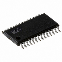
P89LPC9341FDH,512 NXP Semiconductors, P89LPC9341FDH,512 Datasheet - Page 38

P89LPC9341FDH,512
Manufacturer Part Number
P89LPC9341FDH,512
Description
IC 80C51 MCU FLASH 8K 28-TSSOP
Manufacturer
NXP Semiconductors
Series
LPC900r
Datasheet
1.P89LPC9351FA112.pdf
(94 pages)
Specifications of P89LPC9341FDH,512
Program Memory Type
FLASH
Program Memory Size
8KB (8K x 8)
Package / Case
28-TSSOP
Core Processor
8051
Core Size
8-Bit
Speed
18MHz
Connectivity
I²C, SPI, UART/USART
Peripherals
Brown-out Detect/Reset, POR, PWM, WDT
Number Of I /o
26
Ram Size
256 x 8
Voltage - Supply (vcc/vdd)
2.4 V ~ 3.6 V
Data Converters
A/D 8x8b; D/A 2x8b
Oscillator Type
Internal
Operating Temperature
-40°C ~ 85°C
Processor Series
P89LPC
Core
80C51
Data Bus Width
8 bit
Data Ram Size
256 B
Interface Type
I2C, SPI, UART
Maximum Clock Frequency
18 MHz
Number Of Programmable I/os
23
Number Of Timers
2
Operating Supply Voltage
2.4 V to 3.6 V
Maximum Operating Temperature
+ 85 C
Mounting Style
SMD/SMT
3rd Party Development Tools
PK51, CA51, A51, ULINK2
Minimum Operating Temperature
- 40 C
On-chip Adc
2 (8 bit, 4 Channel)
Lead Free Status / RoHS Status
Lead free / RoHS Compliant
For Use With
568-1758 - BOARD EVAL FOR LPC93X MCU FAMILY
Eeprom Size
-
Lead Free Status / Rohs Status
Lead free / RoHS Compliant
Other names
935288632512
NXP Semiconductors
P89LPC9331_9341_9351_9361
Product data sheet
7.17.1 Brownout detection
7.17.2 Power-on detection
7.18.1 Idle mode
7.18.2 Power-down mode
7.18 Power reduction modes
The brownout detect function determines if the power supply voltage drops below a
certain level. Enhanced brownout detection has 3 independent functions: BOD reset,
BOD interrupt and BOD EEPROM/FLASH.
BOD reset is always on except in total Power-down mode. It could not be disabled in
software. BOD interrupt may be enabled or disabled in software. BOD EEPROM/FLASH
is always on, except in Power-down modes and could not be disabled in software.
BOD reset and BOD interrupt, each has four trip voltage levels. BOE1 bit (UCFG1.5) and
BOE0 bit (UCFG1.3) are used as trip point configuration bits of BOD reset. BOICFG1 bit
and BOICFG0 bit in register BODCFG are used as trip point configuration bits of BOD
interrupt. BOD reset voltage should be lower than BOD interrupt trip point. BOD
EEPROM/FLASH is used for flash/Data EEPROM programming/erase protection and has
only 1 trip voltage of 2.4 V. Please refer to P89LPC9331/9341/9351/9361 User manual for
detail configurations.
If brownout detection is enabled the brownout condition occurs when V
brownout trip voltage and is negated when V
For correct activation of brownout detect, the V
Please see
The Power-on detect has a function similar to the brownout detect, but is designed to work
as power comes up initially, before the power supply voltage reaches a level where
brownout detect can work. The POF flag in the RSTSRC register is set to indicate an
initial power-up condition. The POF flag will remain set until cleared by software.
The P89LPC9331/9341/9351/9361 supports three different power reduction modes.
These modes are Idle mode, Power-down mode, and total Power-down mode.
Idle mode leaves peripherals running in order to allow them to activate the processor
when an interrupt is generated. Any enabled interrupt source or reset may terminate Idle
mode.
The Power-down mode stops the oscillator in order to minimize power consumption. The
P89LPC9331/9341/9351/9361 exits Power-down mode via any reset, or certain interrupts.
In Power-down mode, the power supply voltage may be reduced to the data retention
supply voltage V
was entered. SFR contents are not guaranteed after V
therefore it is highly recommended to wake-up the processor via reset in this case. V
must be raised to within the operating range before the Power-down mode is exited.
Table 12 “Static characteristics”
All information provided in this document is subject to legal disclaimers.
DDR
. This retains the RAM contents at the point where Power-down mode
Rev. 5 — 10 January 2011
8-bit microcontroller with accelerated two-clock 80C51 core
P89LPC9331/9341/9351/9361
for specifications.
DD
DD
rises above the brownout trip voltage.
rise and fall times must be observed.
DD
has been lowered to V
DD
© NXP B.V. 2011. All rights reserved.
falls below the
DDR
38 of 94
,
DD


