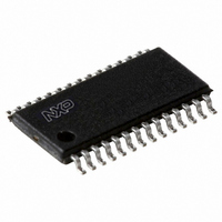
P89LPC9341FDH,512 NXP Semiconductors, P89LPC9341FDH,512 Datasheet - Page 53

P89LPC9341FDH,512
Manufacturer Part Number
P89LPC9341FDH,512
Description
IC 80C51 MCU FLASH 8K 28-TSSOP
Manufacturer
NXP Semiconductors
Series
LPC900r
Datasheet
1.P89LPC9351FA112.pdf
(94 pages)
Specifications of P89LPC9341FDH,512
Program Memory Type
FLASH
Program Memory Size
8KB (8K x 8)
Package / Case
28-TSSOP
Core Processor
8051
Core Size
8-Bit
Speed
18MHz
Connectivity
I²C, SPI, UART/USART
Peripherals
Brown-out Detect/Reset, POR, PWM, WDT
Number Of I /o
26
Ram Size
256 x 8
Voltage - Supply (vcc/vdd)
2.4 V ~ 3.6 V
Data Converters
A/D 8x8b; D/A 2x8b
Oscillator Type
Internal
Operating Temperature
-40°C ~ 85°C
Processor Series
P89LPC
Core
80C51
Data Bus Width
8 bit
Data Ram Size
256 B
Interface Type
I2C, SPI, UART
Maximum Clock Frequency
18 MHz
Number Of Programmable I/os
23
Number Of Timers
2
Operating Supply Voltage
2.4 V to 3.6 V
Maximum Operating Temperature
+ 85 C
Mounting Style
SMD/SMT
3rd Party Development Tools
PK51, CA51, A51, ULINK2
Minimum Operating Temperature
- 40 C
On-chip Adc
2 (8 bit, 4 Channel)
Lead Free Status / RoHS Status
Lead free / RoHS Compliant
For Use With
568-1758 - BOARD EVAL FOR LPC93X MCU FAMILY
Eeprom Size
-
Lead Free Status / Rohs Status
Lead free / RoHS Compliant
Other names
935288632512
NXP Semiconductors
P89LPC9331_9341_9351_9361
Product data sheet
7.26.2 Comparator interrupt
7.26.3 Comparators and power reduction modes
7.27 KBI
Each comparator has an interrupt flag contained in its configuration register. This flag is
set whenever the comparator output changes state. The flag may be polled by software or
may be used to generate an interrupt. The two comparators use one common interrupt
vector. If both comparators enable interrupts, after entering the interrupt service routine,
the user needs to read the flags to determine which comparator caused the interrupt.
Either or both comparators may remain enabled when Power-down or Idle mode is
activated, but both comparators are disabled automatically in Total Power-down mode.
If a comparator interrupt is enabled (except in Total Power-down mode), a change of the
comparator output state will generate an interrupt and wake-up the processor. If the
comparator output to a pin is enabled, the pin should be configured in the push-pull mode
in order to obtain fast switching times while in Power-down mode. The reason is that with
the oscillator stopped, the temporary strong pull-up that normally occurs during switching
on a quasi-bidirectional port pin does not take place.
Comparators consume power in Power-down and Idle modes, as well as in the normal
operating mode. This fact should be taken into account when system power consumption
is an issue. To minimize power consumption, the user can disable the comparators via
PCONA.5, or put the device in Total Power-down mode.
The Keypad Interrupt function (KBI) is intended primarily to allow a single interrupt to be
generated when Port 0 is equal to or not equal to a certain pattern. This function can be
used for bus address recognition or keypad recognition. The user can configure the port
via SFRs for different tasks.
The Keypad Interrupt Mask Register (KBMASK) is used to define which input pins
connected to Port 0 can trigger the interrupt. The Keypad Pattern Register (KBPATN) is
used to define a pattern that is compared to the value of Port 0. The Keypad Interrupt Flag
(KBIF) in the Keypad Interrupt Control Register (KBCON) is set when the condition is
matched while the Keypad Interrupt function is active. An interrupt will be generated if
enabled. The PATN_SEL bit in the Keypad Interrupt Control Register (KBCON) is used to
define equal or not-equal for the comparison.
In order to use the Keypad Interrupt as an original KBI function like in P87LPC76x series,
the user needs to set KBPATN = 0FFH and PATN_SEL = 1 (not equal), then any key
connected to Port 0 which is enabled by the KBMASK register will cause the hardware to
set KBIF and generate an interrupt if it has been enabled. The interrupt may be used to
wake-up the CPU from Idle or Power-down modes. This feature is particularly useful in
handheld, battery-powered systems that need to carefully manage power consumption
yet also need to be convenient to use.
In order to set the flag and cause an interrupt, the pattern on Port 0 must be held longer
than six CCLKs.
All information provided in this document is subject to legal disclaimers.
Rev. 5 — 10 January 2011
8-bit microcontroller with accelerated two-clock 80C51 core
P89LPC9331/9341/9351/9361
© NXP B.V. 2011. All rights reserved.
53 of 94


