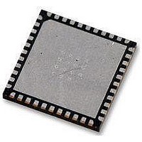
AT89LP52-20MU Atmel, AT89LP52-20MU Datasheet - Page 31

AT89LP52-20MU
Manufacturer Part Number
AT89LP52-20MU
Description
IC MCU 8051 8K FLASH SPI 44VQFN
Manufacturer
Atmel
Series
89LPr
Datasheet
1.AT89LP52-20MU.pdf
(113 pages)
Specifications of AT89LP52-20MU
Core Processor
8051
Core Size
8-Bit
Speed
20MHz
Connectivity
EBI/EMI, I²C, SPI, UART/USART
Peripherals
Brown-out Detect/Reset, POR, PWM, WDT
Number Of I /o
36
Program Memory Size
8KB (8K x 8)
Program Memory Type
FLASH
Ram Size
256 x 8
Voltage - Supply (vcc/vdd)
2.4 V ~ 5.5 V
Oscillator Type
Internal
Operating Temperature
-40°C ~ 85°C
Package / Case
44-VFQFN Exposed Pad
Processor Series
AT89x
Core
8051
Data Bus Width
8 bit
Data Ram Size
256 B
Interface Type
Serial
Maximum Clock Frequency
20 MHz
Number Of Programmable I/os
36
Number Of Timers
3
Operating Supply Voltage
2.7 V to 5.5 V
Maximum Operating Temperature
+ 85 C
Mounting Style
SMD/SMT
Lead Free Status / RoHS Status
Lead free / RoHS Compliant
Eeprom Size
-
Data Converters
-
Lead Free Status / Rohs Status
Details
Available stocks
Company
Part Number
Manufacturer
Quantity
Price
Company:
Part Number:
AT89LP52-20MU
Manufacturer:
Atmel
Quantity:
490
7. Reset
7.1
3709B–MICRO–12/10
Power-on Reset
During reset, all I/O Registers are set to their initial values, the port pins are set to their default
mode, and the program starts execution from the Reset Vector, 0000H. The AT89LP51/52 has
five sources of reset: power-on reset, brown-out reset, external reset, watchdog reset, and soft-
ware reset.
A Power-on Reset (POR) is generated by an on-chip detection circuit. The detection level V
is nominally 1.4V. The POR is activated whenever V
cuit can be used to trigger the start-up reset or to detect a major supply voltage failure. The POR
circuit ensures that the device is reset from power-on. A power-on sequence is shown in
7-1. When V
lasting t
how long the device is kept in POR after V
until after V
activated again, without any delay, when V
Reset (i.e. a cold reset) will set the POF flag in PCON. The internally generated reset can be
extended beyond the power-on period by holding the RST pin active longer than the time-out.
Figure 7-1.
Note:
The start-up timer delay is user-configurable with the Start-up Time User Fuses and depends on
the clock source
after a Brown-out Reset or when waking up from Power-down during internally timed mode. The
start-up delay should be selected to provide enough settling time for V
source. The device operating environment (supply voltage, frequency, temperature, etc.) must
meet the minimum system requirements before the device exits reset and starts normal opera-
tion. The RST pin may be held active externally until these conditions are met.
POR
t
POR
Time-out
DD
is started. When the initialization sequence completes, the start-up timer determines
Internal
Internal
is approximately 143 µs ± 5%.
DD
Reset
Reset
reaches the Brown-out Detector (BOD) threshold voltage V
Power-on Reset Sequence
POL
RST
RST
V
reaches the Power-on Reset threshold voltage V
(Table
DD
t
POR
7-1). The Start-Up Time fuses also control the length of the start-up time
V
POR
V
BOD
(RST Controlled Externally)
DD
t
DD
SUT
AT89LP51/52 - Preliminary
falls below the POR threshold level. A Power-on
rise. The start-up timer does not begin counting
DD
(POL Tied to VCC)
(RST Tied to GND)
is below the detection level. The POR cir-
POR
, an initialization sequence
DD
V
IL
BOD
and the selected clock
t
RHD
. The POR signal is
Figure
POR
31


