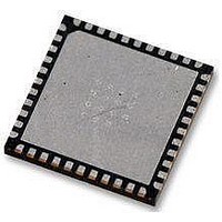
AT89LP52-20MU Atmel, AT89LP52-20MU Datasheet - Page 8

AT89LP52-20MU
Manufacturer Part Number
AT89LP52-20MU
Description
IC MCU 8051 8K FLASH SPI 44VQFN
Manufacturer
Atmel
Series
89LPr
Datasheet
1.AT89LP52-20MU.pdf
(113 pages)
Specifications of AT89LP52-20MU
Core Processor
8051
Core Size
8-Bit
Speed
20MHz
Connectivity
EBI/EMI, I²C, SPI, UART/USART
Peripherals
Brown-out Detect/Reset, POR, PWM, WDT
Number Of I /o
36
Program Memory Size
8KB (8K x 8)
Program Memory Type
FLASH
Ram Size
256 x 8
Voltage - Supply (vcc/vdd)
2.4 V ~ 5.5 V
Oscillator Type
Internal
Operating Temperature
-40°C ~ 85°C
Package / Case
44-VFQFN Exposed Pad
Processor Series
AT89x
Core
8051
Data Bus Width
8 bit
Data Ram Size
256 B
Interface Type
Serial
Maximum Clock Frequency
20 MHz
Number Of Programmable I/os
36
Number Of Timers
3
Operating Supply Voltage
2.7 V to 5.5 V
Maximum Operating Temperature
+ 85 C
Mounting Style
SMD/SMT
Lead Free Status / RoHS Status
Lead free / RoHS Compliant
Eeprom Size
-
Data Converters
-
Lead Free Status / Rohs Status
Details
Available stocks
Company
Part Number
Manufacturer
Quantity
Price
Company:
Part Number:
AT89LP52-20MU
Manufacturer:
Atmel
Quantity:
490
2.2.2
2.2.3
2.2.4
2.2.5
8
AT89LP51/52 - Preliminary
System Clock
Reset
Timer/Counters
Interrupt Handling
by disabling the Compatibility fuse. In Fast mode the CPU fetches one code byte from memory
every clock cycle instead of every three clock cycles. This greatly increases the throughput of
the CPU. Each standard instruction executes in only 1 to 4 clock cycles. See
Summary” on page 75
operations may need to be retuned to achieve the desired results in Fast mode.
By default in Compatibility mode the system clock frequency is divided by 2 from the externally
supplied XTAL1 frequency for compatibility with standard 8051s (12 clocks per machine cycle).
The System Clock Divider can scale the system clock versus the oscillator source (See
6.4 on page
cycle) or the clock may be further divided to reduce the operating frequency. In Fast mode the
clock divider defaults to divide by 1.
The system clock source is selectable between the crystal oscillator, an externally driven clock
and an internal 1.8432 MHz auxiliary oscillator.
The RST pin of the AT89LP51/52 has selectable polarity using the POL pin (formerly EA). When
POL is high the RST pin is active high with a pull-down resistor and when POL is low the RST
pin is active low with a pull-up resistor. For existing AT89S51/52 sockets where EA is tied to
VDD, replacing AT89S51/52 with AT89LP51/52 will maintain the active high reset. Note that
forcing external execution by tying EA low is not supported.
The AT89LP51/52 includes an on-chip Power-On Reset and Brown-out Detector circuit that
ensures that the device is reset from system power up. In most cases a RC startup circuit is not
required on the RST pin, reducing system cost, and the RST pin may be left unconnected if a
board-level reset is not present.
A common prescaler is available to divide the time base for Timer 0, Timer 1, Timer 2 and the
WDT. The TPS
Compatibility mode TPS
machine cycle. The counting rate can be adjusted linearly from the system clock rate to 1/16 of
the system clock rate by changing TPS
clock rate. TPS does not affect Timer 2 in Clock Out or Baud Generator modes.
In Compatibility mode the sampling of the external Timer/Counter pins: T0, T1, T2 and T2EX;
and the external interrupt pins, INT0 and INT1, is also controlled by the prescaler. In Fast mode
these pins are always sampled at the system clock rate.
Both Timer 0 and Timer 1 can toggle their respective counter pins, T0 and T1, when they over-
flow by setting the output enable bits in TCONB.
The Watchdog Timer includes a 7-bit prescaler for longer timeout periods than the AT89S51/52.
Note that in Fast Mode the WDIDLE and DISRTO bits are located in WDTCON and not in
AUXR.
With the addition of the IPH register, the AT89LP51/52 provides four levels of interrupt priority
for greater flexibility in handling multiple interrupts. Also, Fast mode allows for faster interrupt
response due to the shorter instruction execution times.
30). The divide-by-2 can be disabled to operate in X2 mode (6 clocks per machine
3-0
bits in the CLKREG SFR control the prescaler
for more details. Any software delay loops or instruction-based timing
3-0
defaults to 0101B, which causes the timers to count once every
3-0
. In Fast mode TPS
3-0
defaults to 0000B, or the system
(Table 6-2 on page
3709B–MICRO–12/10
“Instruction Set
Section
30). In


