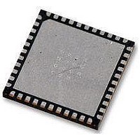
AT89LP52-20MU Atmel, AT89LP52-20MU Datasheet - Page 46

AT89LP52-20MU
Manufacturer Part Number
AT89LP52-20MU
Description
IC MCU 8051 8K FLASH SPI 44VQFN
Manufacturer
Atmel
Series
89LPr
Datasheet
1.AT89LP52-20MU.pdf
(113 pages)
Specifications of AT89LP52-20MU
Core Processor
8051
Core Size
8-Bit
Speed
20MHz
Connectivity
EBI/EMI, I²C, SPI, UART/USART
Peripherals
Brown-out Detect/Reset, POR, PWM, WDT
Number Of I /o
36
Program Memory Size
8KB (8K x 8)
Program Memory Type
FLASH
Ram Size
256 x 8
Voltage - Supply (vcc/vdd)
2.4 V ~ 5.5 V
Oscillator Type
Internal
Operating Temperature
-40°C ~ 85°C
Package / Case
44-VFQFN Exposed Pad
Processor Series
AT89x
Core
8051
Data Bus Width
8 bit
Data Ram Size
256 B
Interface Type
Serial
Maximum Clock Frequency
20 MHz
Number Of Programmable I/os
36
Number Of Timers
3
Operating Supply Voltage
2.7 V to 5.5 V
Maximum Operating Temperature
+ 85 C
Mounting Style
SMD/SMT
Lead Free Status / RoHS Status
Lead free / RoHS Compliant
Eeprom Size
-
Data Converters
-
Lead Free Status / Rohs Status
Details
Available stocks
Company
Part Number
Manufacturer
Quantity
Price
Company:
Part Number:
AT89LP52-20MU
Manufacturer:
Atmel
Quantity:
490
11.1
11.2
46
Mode 0 – 13-bit Timer/Counter
Mode 1 – 16-bit Timer/Counter
AT89LP51/52 - Preliminary
Both Timers in Mode 0 are 8-bit Counters with a divide-by-32 prescaler.
Mode 0 operation as it applies to Timer 1. As the count rolls over from all “1”s to all “0”s, it sets
the Timer interrupt flag TF1. The counter input is enabled to the Timer when TR1 = 1 and either
GATE1 = 0 or INT1 = 1. Setting GATE1 = 1 allows the Timer to be controlled by external input
INT1, to facilitate pulse width measurements. TR1 is a control bit in the Special Function Regis-
ter TCON. GATE1 is in TMOD. The 13-bit register consists of all 8 bits of TH1 and the lower 5
bits of TL1. The upper 3 bits of TL1 are indeterminate and should be ignored. Setting the run flag
(TR1) does not clear the registers.
Figure 11-1. Timer/Counter 1 Mode 0: 13-bit Counter
Mode 0 operation is the same for Timer 0 as for Timer 1, except that TR0, TF0, GATE0 and
INT0 replace the corresponding Timer 1 signals in
one for Timer 1 (TMOD.6) and one for Timer 0 (TMOD.2).
In Mode 1 the Timers are configured for 16-bit operation. The Timer register is run with all 16 bits
and the clock is applied to the combined high and low timer registers (TH1/TL1). As clock pulses
are received, the timer counts up: 0000H, 0001H, 0002H, etc. An overflow occurs on the
FFFFH-to-0000H transition, upon which the overflow flag bit in TCON is set. See
Mode 1 operation is the same for Timer/Counter 0.
Figure 11-2. Timer/Counter 1 Mode 1: 16-bit Counter
OSC
OSC
INT1 Pin
INT1 Pin
GATE1
GATE1
T1 Pin
T1 Pin
÷CDV
÷CDV
Mode 0:
Mode 1:
TR1
TR1
÷TPS
÷TPS
Time-out Period
Time-out Period
C/T = 0
C/T =1
C/T = 0
C/T = 1
Control
Control
=
=
------------------------------------------------- -
System Frequency
------------------------------------------------- -
System Frequency
Figure
8192
65536
(8 Bits)
(5 Bits)
TL1
TL1
11-1. There are two different C/T bits,
(8 Bits)
(8 Bits)
TH1
TH1
×
×
(
TPS
(
TPS
Figure 11-1
+
+
1
TF1
TF1
1
)
)
3709B–MICRO–12/10
Figure
shows the
Inter r up t
Interrupt
11-2.


