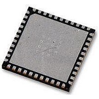
AT89LP52-20MU Atmel, AT89LP52-20MU Datasheet - Page 78

AT89LP52-20MU
Manufacturer Part Number
AT89LP52-20MU
Description
IC MCU 8051 8K FLASH SPI 44VQFN
Manufacturer
Atmel
Series
89LPr
Datasheet
1.AT89LP52-20MU.pdf
(113 pages)
Specifications of AT89LP52-20MU
Core Processor
8051
Core Size
8-Bit
Speed
20MHz
Connectivity
EBI/EMI, I²C, SPI, UART/USART
Peripherals
Brown-out Detect/Reset, POR, PWM, WDT
Number Of I /o
36
Program Memory Size
8KB (8K x 8)
Program Memory Type
FLASH
Ram Size
256 x 8
Voltage - Supply (vcc/vdd)
2.4 V ~ 5.5 V
Oscillator Type
Internal
Operating Temperature
-40°C ~ 85°C
Package / Case
44-VFQFN Exposed Pad
Processor Series
AT89x
Core
8051
Data Bus Width
8 bit
Data Ram Size
256 B
Interface Type
Serial
Maximum Clock Frequency
20 MHz
Number Of Programmable I/os
36
Number Of Timers
3
Operating Supply Voltage
2.7 V to 5.5 V
Maximum Operating Temperature
+ 85 C
Mounting Style
SMD/SMT
Lead Free Status / RoHS Status
Lead free / RoHS Compliant
Eeprom Size
-
Data Converters
-
Lead Free Status / Rohs Status
Details
Available stocks
Company
Part Number
Manufacturer
Quantity
Price
Company:
Part Number:
AT89LP52-20MU
Manufacturer:
Atmel
Quantity:
490
78
AT89LP51/52 - Preliminary
Table 16-1.
Notes:
ORL C, bit
ORL C, /bit
MOV C, bit
MOV bit, C
Branching
JC rel
JNC rel
JB bit, rel
JNB bit, rel
JBC bit, rel
JZ rel
JNZ rel
SJMP rel
ACALL addr11
LCALL addr16
RET
RETI
AJMP addr11
LJMP addr16
JMP @A+DPTR
JMP @A+PC
CJNE A, direct, rel
CJNE A, #data, rel
CJNE Rn, #data, rel
CJNE @Ri, #data, rel
CJNE A, @R0, rel
CJNE A, @R1, rel
DJNZ Rn, rel
DJNZ direct, rel
NOP
1. A clock cycle is one period of the output of the system clock divider. For Fast mode the divider
2. This escaped instruction is an extension to the instruction set.
3. This is the minimum time for MOVX with no wait states. In Compatibility mode an additional 24
defaults to 1, so the clock cycle equals the oscillator period. For Compatibility mode the divider
defaults to 2, so the clock cycle is twice the oscillator period, or conversely the clock count is
half the number of oscillator periods.
clocks are added for the wait state. In Fast mode, 1 clock is added for each wait state (0–3).
(2)
Instruction Execution Times and Exceptions
(2)
(2)
Bytes
2
2
2
2
2
2
3
3
3
2
2
2
2
3
1
1
2
3
1
2
3
3
3
3
3
3
2
3
1
Compatibility
12
12
12
12
12
12
12
12
12
12
12
12
12
12
12
12
12
12
12
12
12
12
12
18
18
12
12
6
6
(1)
Clock Cycles
(Continued)
Fast
2
2
2
2
3
3
4
4
4
3
3
3
3
4
4
4
3
4
2
3
4
4
4
4
4
3
4
1
4
3709B–MICRO–12/10
11,31,51,71,91,
01,21,41,61,81,
Hex Code
A1,C1,E1
B1,D1,F1
D8-DF
B8-BF
B6-B7
A5 B6
A5 B7
A5 73
A0
A2
B5
B4
D5
72
92
40
50
20
30
10
60
70
80
12
22
32
02
73
00


