DSP56309EVM Freescale Semiconductor, DSP56309EVM Datasheet - Page 124
DSP56309EVM
Manufacturer Part Number
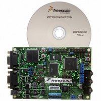
DSP56309EVM
Description
KIT EVALUATION FOR XC56309
Manufacturer
Freescale Semiconductor
Type
DSPr
Specifications of DSP56309EVM
Contents
Module Board, Installation Guide, Power Supply, Cable, Software and more
Description/function
Audio DSPs
Product
Audio Modules
For Use With/related Products
DSP56309
Lead Free Status / RoHS Status
Contains lead / RoHS non-compliant


Host Interface (HI08)
6.7.2 Command Vector Register (CVR)
The host processor uses the CVR, an 8-bit read/write register, to cause the DSP56309 to execute
an interrupt. The host command feature is independent of any of the data transfer mechanisms in
the HI08. It causes execution of any of the 128 possible interrupt routines in the DSP core.
Hardware, software, individual, and stop resets clear the CVR bits.
6.7.3 Interface Status Register (ISR)
The host processor uses the ISR, an 8-bit read-only status register, to interrogate the HI08 status
and flags. The DSP core cannot address the ISR.
6-24
Bit Number
6–0
7
Bit Name
HV[6–0]
Table 6-16. Command Vector Register (CVR) Bit Definitions
HC
HREQ
Figure 6-16. Command Vector Register (CVR)
HC
7
7
Figure 6-17. Interface Status Register (ISR)
Reset Value
—Reserved bit; read as 0; write to 0 for future compatibility.
HV6
$32
0
6
6
DSP56309 User’s Manual, Rev. 1
HV5
5
5
Host Command
The host processor uses the HC bit to handshake the execution of host
command interrupts. Normally, the host processor sets HC to request a
host command interrupt from the DSP56309. When the DSP56309
acknowledges the host command interrupt, HI08 hardware clears the
HC bit. The host processor can read the state of HC to determine when
the host command has been accepted. After setting HC, the host must
not write to the CVR again until the HI08 hardware clears the HC. Setting
the HC bit causes host command pending (HCP) to be set in the HSR.
The host can write to the HC and HV bits in the same write cycle.
Host Vector
Select the host command interrupt address for use by the host command
interrupt logic. When the DSP interrupt control logic recognizes the host
command interrupt, the address of the interrupt routine taken is 2 × HV.
The host can write HC and HV in the same write cycle.
The host processor can select any of the 128 possible interrupt routine
starting addresses in the DSP by writing the interrupt routine address
divided by 2 into the HV bits. This means that the host processor can
force any interrupt handler (ESSI, SCI, IRQA, IRQB, and so forth) and
can use any reserved or otherwise unused addresses (if have been
pre-programmed in the DSP). HV is set to $32 (vector location $064) by
hardware, software, individual, and stop resets.
HV4
HF3
4
4
HV3
HF2
3
3
TRDY TXDE RXDF
HV2
2
2
Description
HV1
1
1
HV0
0
0
Freescale Semiconductor
Related parts for DSP56309EVM
Image
Part Number
Description
Manufacturer
Datasheet
Request
R

Part Number:
Description:
Manufacturer:
Freescale Semiconductor, Inc
Datasheet:
Part Number:
Description:
Manufacturer:
Freescale Semiconductor, Inc
Datasheet:
Part Number:
Description:
Manufacturer:
Freescale Semiconductor, Inc
Datasheet:
Part Number:
Description:
Manufacturer:
Freescale Semiconductor, Inc
Datasheet:
Part Number:
Description:
Manufacturer:
Freescale Semiconductor, Inc
Datasheet:
Part Number:
Description:
Manufacturer:
Freescale Semiconductor, Inc
Datasheet:
Part Number:
Description:
Manufacturer:
Freescale Semiconductor, Inc
Datasheet:
Part Number:
Description:
Manufacturer:
Freescale Semiconductor, Inc
Datasheet:
Part Number:
Description:
Manufacturer:
Freescale Semiconductor, Inc
Datasheet:
Part Number:
Description:
Manufacturer:
Freescale Semiconductor, Inc
Datasheet:
Part Number:
Description:
Manufacturer:
Freescale Semiconductor, Inc
Datasheet:
Part Number:
Description:
Manufacturer:
Freescale Semiconductor, Inc
Datasheet:
Part Number:
Description:
Manufacturer:
Freescale Semiconductor, Inc
Datasheet:
Part Number:
Description:
Manufacturer:
Freescale Semiconductor, Inc
Datasheet:
Part Number:
Description:
Manufacturer:
Freescale Semiconductor, Inc
Datasheet: