DSP56309EVM Freescale Semiconductor, DSP56309EVM Datasheet - Page 49
DSP56309EVM
Manufacturer Part Number
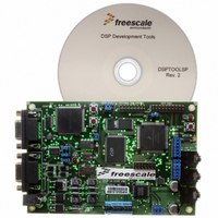
DSP56309EVM
Description
KIT EVALUATION FOR XC56309
Manufacturer
Freescale Semiconductor
Type
DSPr
Specifications of DSP56309EVM
Contents
Module Board, Installation Guide, Power Supply, Cable, Software and more
Description/function
Audio DSPs
Product
Audio Modules
For Use With/related Products
DSP56309
Lead Free Status / RoHS Status
Contains lead / RoHS non-compliant


3.4 Dynamic Memory Configuration Switching
Do not change the OMR[MS] bit when the SR[CE] bit is set. The Instruction Cache occupies the
top 1 K of what is otherwise Program RAM, and to switch memory into or out of Program RAM
when the cache is enabled can cause conflicts. To change the MS bit when CE is set:
Because an interrupt could cause the DSP to fetch instructions out of sequence and might violate
the switch condition, special care should be taken in relation to the interrupt vector routines.
3.5 Sixteen-Bit Compatibility Mode Configuration
The sixteen-bit compatibility (SC) mode allows the DSP56309 to use DSP56000 object code
without change. The SC bit (Bit 13 in the SR) is used to switch from the default 24-bit mode to
this special 16-bit mode. SC is cleared by reset. You must set this bit to select the SC mode. The
address ranges described in the previous sections apply in the SC mode with regard to the
reallocation of X and Y data memory to program memory in MS mode, but the maximum
addressing ranges are limited to $FFFF, and all data and program code are 16 bits wide.
Freescale Semiconductor
1.
2.
3.
Clear CE.
Change MS.
Set CE.
To ensure that dynamic switching is trouble-free, do not allow any
accesses (including instruction fetches) to or from the affected address
ranges in program and data memories during the switch cycle.
Pay special attention when executing a memory switch routine using the
OnCE port. Running the switch routine in trace mode, for example, can
cause the switch to complete after the MS/MSW bits change while the DSP
is in Debug mode. As a result, subsequent instructions may be fetched
according to the new memory configuration (after the switch) and thus
may execute improperly.
DSP56309 User’s Manual, Rev. 1
CAUTION
CAUTION
Dynamic Memory Configuration Switching
3-5
Related parts for DSP56309EVM
Image
Part Number
Description
Manufacturer
Datasheet
Request
R

Part Number:
Description:
Manufacturer:
Freescale Semiconductor, Inc
Datasheet:
Part Number:
Description:
Manufacturer:
Freescale Semiconductor, Inc
Datasheet:
Part Number:
Description:
Manufacturer:
Freescale Semiconductor, Inc
Datasheet:
Part Number:
Description:
Manufacturer:
Freescale Semiconductor, Inc
Datasheet:
Part Number:
Description:
Manufacturer:
Freescale Semiconductor, Inc
Datasheet:
Part Number:
Description:
Manufacturer:
Freescale Semiconductor, Inc
Datasheet:
Part Number:
Description:
Manufacturer:
Freescale Semiconductor, Inc
Datasheet:
Part Number:
Description:
Manufacturer:
Freescale Semiconductor, Inc
Datasheet:
Part Number:
Description:
Manufacturer:
Freescale Semiconductor, Inc
Datasheet:
Part Number:
Description:
Manufacturer:
Freescale Semiconductor, Inc
Datasheet:
Part Number:
Description:
Manufacturer:
Freescale Semiconductor, Inc
Datasheet:
Part Number:
Description:
Manufacturer:
Freescale Semiconductor, Inc
Datasheet:
Part Number:
Description:
Manufacturer:
Freescale Semiconductor, Inc
Datasheet:
Part Number:
Description:
Manufacturer:
Freescale Semiconductor, Inc
Datasheet:
Part Number:
Description:
Manufacturer:
Freescale Semiconductor, Inc
Datasheet: