DSP56309EVM Freescale Semiconductor, DSP56309EVM Datasheet - Page 197
DSP56309EVM
Manufacturer Part Number
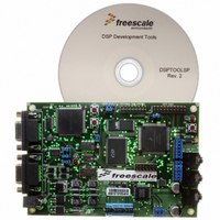
DSP56309EVM
Description
KIT EVALUATION FOR XC56309
Manufacturer
Freescale Semiconductor
Type
DSPr
Specifications of DSP56309EVM
Contents
Module Board, Installation Guide, Power Supply, Cable, Software and more
Description/function
Audio DSPs
Product
Audio Modules
For Use With/related Products
DSP56309
Lead Free Status / RoHS Status
Contains lead / RoHS non-compliant


9.3 Operating Modes
Each timer has operating modes that meet a variety of system requirements, as follows:
Note:
9.3.1 Triple Timer Modes
For all triple timer modes, the following points are true:
9.3.1.1 Timer GPIO (Mode 0)
In Mode 0, the timer generates an internal interrupt when a counter value is reached, if the timer
compare interrupt is enabled (see Figure 9-3 and Figure 9-4). When the counter equals the
TCPR value, TCSR[TCF] is set and a compare interrupt is generated if the TCSR[TCIE] bit is
Freescale Semiconductor
TC3
0
Timer
— GPIO, mode 0: Internal timer interrupt generated by the internal clock
— Pulse, mode 1: External timer pulse generated by the internal clock
— Toggle, mode 2: Output timing signal toggled by the internal clock
— Event counter, mode 3: Internal timer interrupt generated by an external clock
Measurement
— Input width, mode 4: Input pulse width measurement
— Input period, mode 5: Input signal period measurement
— Capture, mode 6: Capture external signal
PWM, mode 7: Pulse width modulation
Watchdog
— Pulse, mode 9: Output pulse, internal clock
— Toggle, mode 10: Output toggle, internal clock
The TCSR[TE] bit is set to clear the counter and enable the timer. Clearing TCSR[TE]
disables the timer.
The value to which the timer is to count is loaded into the TCPR. (This is true for all
modes except the measurement modes (modes 4 through 6).
The counter is loaded with the TLR value on the first clock.
If the counter overflows, TCSR[TOF] is set, and if TCSR[TOIE] is set, an overflow
interrupt is generated.
You can read the counter contents at any time from the Timer Count Register (TCR).
To ensure proper operation, the TCSR TC[3–0] bits should be changed only when the
timer is disabled (that is, when TCSR[TE] is cleared).
TC2
Bit Settings
0
TC1
0
TC0
0
Mode
DSP56309 User’s Manual, Rev. 1
0
Name
GPIO
Mode Characteristics
Function
Timer
GPIO
TIO
Operating Modes
Internal
Clock
9-5
Related parts for DSP56309EVM
Image
Part Number
Description
Manufacturer
Datasheet
Request
R

Part Number:
Description:
Manufacturer:
Freescale Semiconductor, Inc
Datasheet:
Part Number:
Description:
Manufacturer:
Freescale Semiconductor, Inc
Datasheet:
Part Number:
Description:
Manufacturer:
Freescale Semiconductor, Inc
Datasheet:
Part Number:
Description:
Manufacturer:
Freescale Semiconductor, Inc
Datasheet:
Part Number:
Description:
Manufacturer:
Freescale Semiconductor, Inc
Datasheet:
Part Number:
Description:
Manufacturer:
Freescale Semiconductor, Inc
Datasheet:
Part Number:
Description:
Manufacturer:
Freescale Semiconductor, Inc
Datasheet:
Part Number:
Description:
Manufacturer:
Freescale Semiconductor, Inc
Datasheet:
Part Number:
Description:
Manufacturer:
Freescale Semiconductor, Inc
Datasheet:
Part Number:
Description:
Manufacturer:
Freescale Semiconductor, Inc
Datasheet:
Part Number:
Description:
Manufacturer:
Freescale Semiconductor, Inc
Datasheet:
Part Number:
Description:
Manufacturer:
Freescale Semiconductor, Inc
Datasheet:
Part Number:
Description:
Manufacturer:
Freescale Semiconductor, Inc
Datasheet:
Part Number:
Description:
Manufacturer:
Freescale Semiconductor, Inc
Datasheet:
Part Number:
Description:
Manufacturer:
Freescale Semiconductor, Inc
Datasheet: