DSP56309EVM Freescale Semiconductor, DSP56309EVM Datasheet - Page 202
DSP56309EVM
Manufacturer Part Number
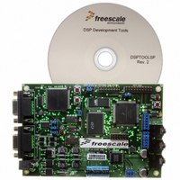
DSP56309EVM
Description
KIT EVALUATION FOR XC56309
Manufacturer
Freescale Semiconductor
Type
DSPr
Specifications of DSP56309EVM
Contents
Module Board, Installation Guide, Power Supply, Cable, Software and more
Description/function
Audio DSPs
Product
Audio Modules
For Use With/related Products
DSP56309
Lead Free Status / RoHS Status
Contains lead / RoHS non-compliant


Triple Timer Module
9.3.1.4 Timer Event Counter (Mode 3)
In Mode 3, the timer counts external events and issues an interrupt (if interrupt enable bits are set)
when the timer counts a preset number of events. The timer clock signal can be taken from either
the TIO input signal or the prescaler clock output. If an external clock is used, it must be
internally synchronized to the internal clock, and its frequency must be less than the DSP56309
internal operating frequency divided by 4. The value of the TCSR[INV] bit determines whether
low-to-high (0 to 1) transitions or high-to-low (1 to 0) transitions increment the counter. If the
INV bit is set, high-to-low transitions increment the counter. If the INV bit is cleared,
low-to-high transitions increment the counter.
When the counter matches the value contained in the TCPR, TCSR[TCF] is set and a compare
interrupt is generated if the TCSR[TCIE] bit is set. If the TCSR[TRM] bit is set, the counter is
loaded with the value of the TLR when the next timer clock is received, and the count is resumed.
If the TCSR[TRM] bit is cleared, the counter continues to increment on each timer clock. This
process repeats until the timer is disabled.
9-10
TC3
0
Mode 3 (internal clock): TRM = 1
N = write preload
M = write compare
TE
Clock
(TIO pin or prescale CLK)
TLR
Counter (TCR)
TCPR
TCF (Compare Interrupt if TCIE = 1)
NOTE: If INV = 1, counter is clocked on 1-to-0 clock transitions, instead of 0-to-1 transitions.
TC2
Bit Settings
0
TC1
1
TC0
N
M
Figure 9-9. Event Counter Mode, TRM = 1
1
0
first event
Mode
DSP56309 User’s Manual, Rev. 1
3
N
Event Counter
Name
N + 1
Mode Characteristics
M
Function
Timer
N
if clock source
is from TIO pin,
TIO < CPUCLK + 4
interrupts every
M - N clock
periods
Freescale Semiconductor
Input
TIO
N + 1
External
Clock
Related parts for DSP56309EVM
Image
Part Number
Description
Manufacturer
Datasheet
Request
R

Part Number:
Description:
Manufacturer:
Freescale Semiconductor, Inc
Datasheet:
Part Number:
Description:
Manufacturer:
Freescale Semiconductor, Inc
Datasheet:
Part Number:
Description:
Manufacturer:
Freescale Semiconductor, Inc
Datasheet:
Part Number:
Description:
Manufacturer:
Freescale Semiconductor, Inc
Datasheet:
Part Number:
Description:
Manufacturer:
Freescale Semiconductor, Inc
Datasheet:
Part Number:
Description:
Manufacturer:
Freescale Semiconductor, Inc
Datasheet:
Part Number:
Description:
Manufacturer:
Freescale Semiconductor, Inc
Datasheet:
Part Number:
Description:
Manufacturer:
Freescale Semiconductor, Inc
Datasheet:
Part Number:
Description:
Manufacturer:
Freescale Semiconductor, Inc
Datasheet:
Part Number:
Description:
Manufacturer:
Freescale Semiconductor, Inc
Datasheet:
Part Number:
Description:
Manufacturer:
Freescale Semiconductor, Inc
Datasheet:
Part Number:
Description:
Manufacturer:
Freescale Semiconductor, Inc
Datasheet:
Part Number:
Description:
Manufacturer:
Freescale Semiconductor, Inc
Datasheet:
Part Number:
Description:
Manufacturer:
Freescale Semiconductor, Inc
Datasheet:
Part Number:
Description:
Manufacturer:
Freescale Semiconductor, Inc
Datasheet: