DSP56309EVM Freescale Semiconductor, DSP56309EVM Datasheet - Page 141
DSP56309EVM
Manufacturer Part Number
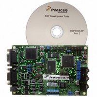
DSP56309EVM
Description
KIT EVALUATION FOR XC56309
Manufacturer
Freescale Semiconductor
Type
DSPr
Specifications of DSP56309EVM
Contents
Module Board, Installation Guide, Power Supply, Cable, Software and more
Description/function
Audio DSPs
Product
Audio Modules
For Use With/related Products
DSP56309
Lead Free Status / RoHS Status
Contains lead / RoHS non-compliant


7.4 Operating Modes: Normal, Network, and On-Demand
The ESSI has three basic operating modes and several data and operation formats. These modes
are programmed via the ESSI control registers. The data and operation formats available to the
ESSI are selected when you set or clear control bits in the CRA and CRB. These control bits are
WL[2–1], MOD, SYN, FSL[1–0], FSR, FSP, CKP, and SHFD.
7.4.1 Normal/Network/On-Demand Mode Selection
To select either Normal mode or Network mode, clear or set CRB[MOD]. In Normal mode, the
ESSI sends or receives one data word per frame (per enabled receiver or transmitter). In Network
mode, 2 to 32 time slots per frame can be selected. During each frame, 0 to 32 data words are
received or transmitted (from each enabled receiver or transmitter). In either case, the transfers
are periodic.
The Normal mode typically transfers data to or from a single device. Network mode is typically
used in time division multiplexed networks of CODECs or DSPs with multiple words per frame.
Network mode has a submode called On-Demand mode. Set the CRB[MOD] for Network mode,
and set the frame rate divider to 0 (DC = $00000) to select On-Demand mode. This submode
does not generate a periodic frame sync. A frame sync pulse is generated only when data is
available to transmit. The frame sync signal indicates the first time slot in the frame. On-Demand
mode requires that the transmit frame sync be internal (output) and the receive frame sync be
external (input). For simplex operation, Synchronous mode could be used; however, for
full-duplex operation, Asynchronous mode must be used. You can enable data transmission that
is data-driven by writing data into each TX. Although the ESSI is double-buffered, only one
word can be written to each TX, even if the transmit shift register is empty. The receive and
transmit interrupts function normally, using TDE and RDF; however, transmit underruns are
impossible for On-Demand transmission and are disabled. This mode is useful for interfacing
with codecs requiring a continuous clock.
Note:
Freescale Semiconductor
After the first transmit, subsequent transmit values are typically loaded into TXnn by the
ISR (one value per register per interrupt). Therefore, if N items are to be sent from a
particular TXnn, the ISR needs to load the transmit register (N – 1) times. Steps 2c and
2d can be performed in step 2a as a single instruction. If an interrupt trigger event
occurs before all interrupt trigger configuration steps are performed, the event is ignored
and not queued. If interrupts derived from the core or other peripherals need to be
enabled at the same time as ESSI interrupts, step 2f should be performed last.
When the ESSI transmits data in On-Demand mode (that is, MOD = 1 in the CRB and
DC[4–0] = $00000 in the CRA) with WL[2–0] = 100, the transmission does not work
properly. To ensure correct operation, do not use On-Demand mode with the WL[2–0]
= 100 32-bit word length mode.
DSP56309 User’s Manual, Rev. 1
Operating Modes: Normal, Network, and On-Demand
7-9
Related parts for DSP56309EVM
Image
Part Number
Description
Manufacturer
Datasheet
Request
R

Part Number:
Description:
Manufacturer:
Freescale Semiconductor, Inc
Datasheet:
Part Number:
Description:
Manufacturer:
Freescale Semiconductor, Inc
Datasheet:
Part Number:
Description:
Manufacturer:
Freescale Semiconductor, Inc
Datasheet:
Part Number:
Description:
Manufacturer:
Freescale Semiconductor, Inc
Datasheet:
Part Number:
Description:
Manufacturer:
Freescale Semiconductor, Inc
Datasheet:
Part Number:
Description:
Manufacturer:
Freescale Semiconductor, Inc
Datasheet:
Part Number:
Description:
Manufacturer:
Freescale Semiconductor, Inc
Datasheet:
Part Number:
Description:
Manufacturer:
Freescale Semiconductor, Inc
Datasheet:
Part Number:
Description:
Manufacturer:
Freescale Semiconductor, Inc
Datasheet:
Part Number:
Description:
Manufacturer:
Freescale Semiconductor, Inc
Datasheet:
Part Number:
Description:
Manufacturer:
Freescale Semiconductor, Inc
Datasheet:
Part Number:
Description:
Manufacturer:
Freescale Semiconductor, Inc
Datasheet:
Part Number:
Description:
Manufacturer:
Freescale Semiconductor, Inc
Datasheet:
Part Number:
Description:
Manufacturer:
Freescale Semiconductor, Inc
Datasheet:
Part Number:
Description:
Manufacturer:
Freescale Semiconductor, Inc
Datasheet: