DSP56309EVM Freescale Semiconductor, DSP56309EVM Datasheet - Page 183
DSP56309EVM
Manufacturer Part Number
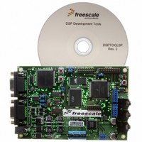
DSP56309EVM
Description
KIT EVALUATION FOR XC56309
Manufacturer
Freescale Semiconductor
Type
DSPr
Specifications of DSP56309EVM
Contents
Module Board, Installation Guide, Power Supply, Cable, Software and more
Description/function
Audio DSPs
Product
Audio Modules
For Use With/related Products
DSP56309
Lead Free Status / RoHS Status
Contains lead / RoHS non-compliant


8.6.2 SCI Status Register (SSR)
The SSR is a read-only register that indicates the status of the SCI.
Freescale Semiconductor
Number
23–8
Bit
7
6
5
R8
23
15
7
Name
—Reserved bit; read as 0; write to 0 for future compatibility.
Bit
PE
R8
FE
FE
22
14
6
Reset
Value
Table 8-4. SCI Status Register (SSR) Bit Definitions
0
0
0
0
Reserved. Write to 0 for future compatibility.
Received Bit 8
In 11-bit Asynchronous Multidrop mode, the R8 bit indicates whether the received byte
is an address or data. R8 is set for addresses and is cleared for data. R8 is not affected
by reads of the SRX or SCI status register. A hardware RESET signal, a software
RESET instruction, an SCI individual reset, or a STOP instruction clears R8.
Framing Error Flag
In Asynchronous mode, FE is set when no stop bit is detected in the data string
received. FE and RDRE are set simultaneously when the received word is transferred to
the SRX. However, the FE flag inhibits further transfer of data into the SRX until it is
cleared. FE is cleared when the SCI status register is read followed by a read of the
SRX. A hardware RESET signal, a software RESET instruction, an SCI individual reset,
or a STOP instruction clears FE. In 8-bit Synchronous mode, FE is always cleared. If the
byte received causes both framing and overrun errors, the SCI receiver recognizes only
the overrun error.
Parity Error
In 11-bit Asynchronous modes, PE is set when an incorrect parity bit is detected in the
received character. PE and RDRF are set simultaneously when the received word is
transferred to the SRX. If PE is set, further data transfer into the SRX is not inhibited. PE
is cleared when the SCI status register is read, followed by a read of SRX. A hardware
RESET signal, a software RESET instruction, an SCI individual reset, or a STOP
instruction also clears PE. In 10-bit Asynchronous mode, 11-bit multidrop mode, and
8-bit Synchronous mode, the PE bit is always cleared since there is no parity bit in these
modes. If the byte received causes both parity and overrun errors, the SCI receiver
recognizes only the overrun error.
PE
21
13
5
Table 8-3. SCI Status Register
DSP56309 User’s Manual, Rev. 1
OR
20
12
4
IDLE
19
11
3
Description
RDRF
18
10
2
TDRE
SCI Programming Model
17
9
1
TRNE
16
8
0
8-15
Related parts for DSP56309EVM
Image
Part Number
Description
Manufacturer
Datasheet
Request
R

Part Number:
Description:
Manufacturer:
Freescale Semiconductor, Inc
Datasheet:
Part Number:
Description:
Manufacturer:
Freescale Semiconductor, Inc
Datasheet:
Part Number:
Description:
Manufacturer:
Freescale Semiconductor, Inc
Datasheet:
Part Number:
Description:
Manufacturer:
Freescale Semiconductor, Inc
Datasheet:
Part Number:
Description:
Manufacturer:
Freescale Semiconductor, Inc
Datasheet:
Part Number:
Description:
Manufacturer:
Freescale Semiconductor, Inc
Datasheet:
Part Number:
Description:
Manufacturer:
Freescale Semiconductor, Inc
Datasheet:
Part Number:
Description:
Manufacturer:
Freescale Semiconductor, Inc
Datasheet:
Part Number:
Description:
Manufacturer:
Freescale Semiconductor, Inc
Datasheet:
Part Number:
Description:
Manufacturer:
Freescale Semiconductor, Inc
Datasheet:
Part Number:
Description:
Manufacturer:
Freescale Semiconductor, Inc
Datasheet:
Part Number:
Description:
Manufacturer:
Freescale Semiconductor, Inc
Datasheet:
Part Number:
Description:
Manufacturer:
Freescale Semiconductor, Inc
Datasheet:
Part Number:
Description:
Manufacturer:
Freescale Semiconductor, Inc
Datasheet:
Part Number:
Description:
Manufacturer:
Freescale Semiconductor, Inc
Datasheet: