DSP56309EVM Freescale Semiconductor, DSP56309EVM Datasheet - Page 140
DSP56309EVM
Manufacturer Part Number
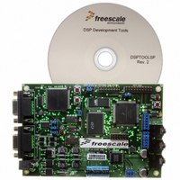
DSP56309EVM
Description
KIT EVALUATION FOR XC56309
Manufacturer
Freescale Semiconductor
Type
DSPr
Specifications of DSP56309EVM
Contents
Module Board, Installation Guide, Power Supply, Cable, Software and more
Description/function
Audio DSPs
Product
Audio Modules
For Use With/related Products
DSP56309
Lead Free Status / RoHS Status
Contains lead / RoHS non-compliant


Enhanced Synchronous Serial Interface (ESSI)
Note:
To configure an ESSI exception, perform the following steps:
7-8
1.
2.
exception occurs regardless of the transmit mask register setting. The transmit last slot
interrupt can signal that the transmit mask slot register can be reset, the DMA channels
can be reconfigured, and data memory pointers can be reassigned. Using the Transmit Last
Slot interrupt guarantees that the previous frame is serviced with the previous frame
settings and the new frame is serviced with the new frame settings without
synchronization problems.
ESSI transmit data:
Occurs when the transmit interrupt is enabled, at least one of the enabled transmit data
registers is empty, and no transmitter error conditions exist. Write to all the enabled TX
registers or to the TSR to clear this interrupt. This error-free interrupt uses a fast interrupt
service routine for minimum overhead (if no more than two transmitters are used).
Configure the interrupt service routine (ISR):
a.
b.
c.
Configure interrupt trigger; preload transmit data
a.
b.
c.
d.
e.
f.
The example material to the right of the steps shows register settings for configuring an
ESSI0 transmit interrupt using transmitter 0. The order of the steps is optional except
that the interrupt trigger configuration must not be completed until the ISR
configuration is complete. Since step 2c may cause an immediate transmit without
generating an interrupt, perform the transmit data preload in step 2b before step 2c to
ensure that valid data is sent in the first transmission.
The maximum transmit last slot interrupt service time should not exceed
N – 1 ESSI bits service time (where N is the number of bits in a slot).
Load vector base address register
Define I_VEC to be equal to the VBA value (if that is nonzero). If it is defined,
I_VEC must be defined for the assembler before the interrupt equate file is
included.
Load the exception vector table entry: two-word fast interrupt, or jump/branch to
subroutine (long interrupt).
Enable and prioritize overall peripheral interrupt functionality.
Write data to all enabled transmit registers.
Enable a peripheral interrupt-generating function.
Enable a specific peripheral interrupt.
Enable peripheral and associated signals.
Unmask interrupts at the global level.
DSP56309 User’s Manual, Rev. 1
VBA (b23:8)
p:I_SI0TD
IPRP (S0L1:0)
TX00
CRB0 (TIE)
PCRC (PC[5–0])
SR (I1–0)
CRB (TE0)
Freescale Semiconductor
Related parts for DSP56309EVM
Image
Part Number
Description
Manufacturer
Datasheet
Request
R

Part Number:
Description:
Manufacturer:
Freescale Semiconductor, Inc
Datasheet:
Part Number:
Description:
Manufacturer:
Freescale Semiconductor, Inc
Datasheet:
Part Number:
Description:
Manufacturer:
Freescale Semiconductor, Inc
Datasheet:
Part Number:
Description:
Manufacturer:
Freescale Semiconductor, Inc
Datasheet:
Part Number:
Description:
Manufacturer:
Freescale Semiconductor, Inc
Datasheet:
Part Number:
Description:
Manufacturer:
Freescale Semiconductor, Inc
Datasheet:
Part Number:
Description:
Manufacturer:
Freescale Semiconductor, Inc
Datasheet:
Part Number:
Description:
Manufacturer:
Freescale Semiconductor, Inc
Datasheet:
Part Number:
Description:
Manufacturer:
Freescale Semiconductor, Inc
Datasheet:
Part Number:
Description:
Manufacturer:
Freescale Semiconductor, Inc
Datasheet:
Part Number:
Description:
Manufacturer:
Freescale Semiconductor, Inc
Datasheet:
Part Number:
Description:
Manufacturer:
Freescale Semiconductor, Inc
Datasheet:
Part Number:
Description:
Manufacturer:
Freescale Semiconductor, Inc
Datasheet:
Part Number:
Description:
Manufacturer:
Freescale Semiconductor, Inc
Datasheet:
Part Number:
Description:
Manufacturer:
Freescale Semiconductor, Inc
Datasheet: