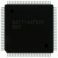
HD6417144F50V Renesas Electronics America, HD6417144F50V Datasheet - Page 30

HD6417144F50V
Manufacturer Part Number
HD6417144F50V
Description
IC SUPERH MCU ROMLESS 112QFP
Manufacturer
Renesas Electronics America
Series
SuperH® SH7144r
Datasheet
1.HD64F7144F50V.pdf
(932 pages)
Specifications of HD6417144F50V
Core Processor
SH-2
Core Size
32-Bit
Speed
50MHz
Connectivity
EBI/EMI, I²C, SCI
Peripherals
DMA, POR, PWM, WDT
Number Of I /o
74
Program Memory Type
ROMless
Ram Size
8K x 8
Voltage - Supply (vcc/vdd)
3 V ~ 3.6 V
Data Converters
A/D 8x10b
Oscillator Type
Internal
Operating Temperature
-20°C ~ 75°C
Package / Case
112-QFP
For Use With
HS0005KCU11H - EMULATOR E10A-USB H8S(X),SH2(A)EDK7145 - DEV EVALUATION KIT SH7145
Lead Free Status / RoHS Status
Lead free / RoHS Compliant
Eeprom Size
-
Program Memory Size
-
Available stocks
Company
Part Number
Manufacturer
Quantity
Price
Company:
Part Number:
HD6417144F50V
Manufacturer:
Renesas Electronics America
Quantity:
10 000
- Current page: 30 of 932
- Download datasheet (6Mb)
Figure 11.25 Example of Phase Counting Mode 1 Operation .................................................... 277
Figure 11.26 Example of Phase Counting Mode 2 Operation .................................................... 278
Figure 11.27 Example of Phase Counting Mode 3 Operation .................................................... 279
Figure 11.28 Example of Phase Counting Mode 4 Operation .................................................... 280
Figure 11.29 Phase Counting Mode Application Example......................................................... 281
Figure 11.30 Procedure for Selecting Reset-Synchronized PWM Mode.................................... 283
Figure 11.31 Reset-Synchronized PWM Mode Operation Example
Figure 11.32 Block Diagram of Channels 3 and 4 in Complementary PWM Mode .................. 287
Figure 11.33 Example of Complementary PWM Mode Setting Procedure................................ 288
Figure 11.34 Complementary PWM Mode Counter Operation.................................................. 290
Figure 11.35 Example of Complementary PWM Mode Operation ............................................ 292
Figure 11.36 Example of PWM Cycle Updating........................................................................ 294
Figure 11.37 Example of Data Update in Complementary PWM Mode .................................... 296
Figure 11.38 Example of Initial Output in Complementary PWM Mode (1)............................. 297
Figure 11.39 Example of Initial Output in Complementary PWM Mode (2)............................. 298
Figure 11.40 Example of Complementary PWM Mode Waveform Output (1) ......................... 300
Figure 11.41 Example of Complementary PWM Mode Waveform Output (2) ......................... 300
Figure 11.42 Example of Complementary PWM Mode Waveform Output (3) ......................... 301
Figure 11.43 Example of Complementary PWM Mode 0% and 100% Waveform Output
Figure 11.44 Example of Complementary PWM Mode 0% and 100% Waveform Output
Figure 11.45 Example of Complementary PWM Mode 0% and 100% Waveform Output
Figure 11.46 Example of Complementary PWM Mode 0% and 100% Waveform Output
Figure 11.47 Example of Complementary PWM Mode 0% and 100% Waveform Output
Figure 11.48 Example of Toggle Output Waveform Synchronized with PWM Output............. 304
Figure 11.49 Counter Clearing Synchronized with Another Channel ........................................ 305
Figure 11.50 Example of Output Phase Switching by External Input (1)................................... 306
Figure 11.51 Example of Output Phase Switching by External Input (2)................................... 307
Figure 11.52 Example of Output Phase Switching by Means of UF, VF, WF Bit Settings
Figure 11.53 Example of Output Phase Switching by Means of UF, VF, WF Bit Settings
Figure 11.54 Count Timing in Internal Clock Operation............................................................ 313
Figure 11.55 Count Timing in External Clock Operation........................................................... 313
Figure 11.56 Count Timing in External Clock Operation (Phase Counting Mode).................... 313
Rev.4.00 Mar. 27, 2008 Page xxviii of xliv
REJ09B0108-0400
(When TOCR’s OLSN = 1 and OLSP = 1) ........................................................... 284
(1) .......................................................................................................................... 301
(2) .......................................................................................................................... 302
(3) .......................................................................................................................... 302
(4) .......................................................................................................................... 303
(5) .......................................................................................................................... 303
(1) .......................................................................................................................... 307
(2) .......................................................................................................................... 308
Related parts for HD6417144F50V
Image
Part Number
Description
Manufacturer
Datasheet
Request
R

Part Number:
Description:
KIT STARTER FOR M16C/29
Manufacturer:
Renesas Electronics America
Datasheet:

Part Number:
Description:
KIT STARTER FOR R8C/2D
Manufacturer:
Renesas Electronics America
Datasheet:

Part Number:
Description:
R0K33062P STARTER KIT
Manufacturer:
Renesas Electronics America
Datasheet:

Part Number:
Description:
KIT STARTER FOR R8C/23 E8A
Manufacturer:
Renesas Electronics America
Datasheet:

Part Number:
Description:
KIT STARTER FOR R8C/25
Manufacturer:
Renesas Electronics America
Datasheet:

Part Number:
Description:
KIT STARTER H8S2456 SHARPE DSPLY
Manufacturer:
Renesas Electronics America
Datasheet:

Part Number:
Description:
KIT STARTER FOR R8C38C
Manufacturer:
Renesas Electronics America
Datasheet:

Part Number:
Description:
KIT STARTER FOR R8C35C
Manufacturer:
Renesas Electronics America
Datasheet:

Part Number:
Description:
KIT STARTER FOR R8CL3AC+LCD APPS
Manufacturer:
Renesas Electronics America
Datasheet:

Part Number:
Description:
KIT STARTER FOR RX610
Manufacturer:
Renesas Electronics America
Datasheet:

Part Number:
Description:
KIT STARTER FOR R32C/118
Manufacturer:
Renesas Electronics America
Datasheet:

Part Number:
Description:
KIT DEV RSK-R8C/26-29
Manufacturer:
Renesas Electronics America
Datasheet:

Part Number:
Description:
KIT STARTER FOR SH7124
Manufacturer:
Renesas Electronics America
Datasheet:

Part Number:
Description:
KIT STARTER FOR H8SX/1622
Manufacturer:
Renesas Electronics America
Datasheet:

Part Number:
Description:
KIT DEV FOR SH7203
Manufacturer:
Renesas Electronics America
Datasheet:


