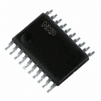
PCA9665PW,118 NXP Semiconductors, PCA9665PW,118 Datasheet - Page 15

PCA9665PW,118
Manufacturer Part Number
PCA9665PW,118
Description
IC CNTRLR PARALLEL/I2C 20TSSOP
Manufacturer
NXP Semiconductors
Datasheet
1.PCA9665D118.pdf
(90 pages)
Specifications of PCA9665PW,118
Package / Case
20-TSSOP
Controller Type
I²C Bus Controller
Interface
I²C
Voltage - Supply
2.3 V ~ 3.6 V
Current - Supply
100µA
Operating Temperature
-40°C ~ 85°C
Mounting Type
Surface Mount
Maximum Operating Temperature
+ 85 C
Minimum Operating Temperature
- 40 C
Mounting Style
SMD/SMT
Lead Free Status / RoHS Status
Lead free / RoHS Compliant
Lead Free Status / RoHS Status
Lead free / RoHS Compliant, Lead free / RoHS Compliant
Other names
568-4070-2
935279244118
PCA9665PW-T
PCA9665PW-T
935279244118
PCA9665PW-T
PCA9665PW-T
NXP Semiconductors
PCA9665_3
Product data sheet
7.3.2.6 The I
I2CMODE is an 8-bit read/write register. It contains the control bits that select the correct
timing parameters when the device is used in master mode (AC[1:0]). Timing parameters
involved with AC[1:0] are t
Table 23.
Table 24.
Remark: Change from an I
for example) will cause the HIGH and LOW timings of SCL to be violated. It is then
required to program the I2CSCLL and I2CSCLH registers with values in accordance with
the selected mode.
Table 25.
[1]
[2]
Bit
7:2
1:0
I2CSCLL
(hexadecimal)
9D
2C
11
0E
I2CSCLL and I2CSCLH values in the table also represents the minimum values that can be used for the
corresponding I
Using the formula
7
-
2
C-bus mode register, I2CMODE (indirect address 06h)
Symbol
-
AC[1:0]
I2CMODE - I
I2CMODE - I
I
2
C-bus mode selection example
6
-
2
C-bus mode. Use of lower values will cause the minimum values to be loaded.
I2CSCLH
(hexadecimal)
86
14
09
05
f
SCL
Rev. 03 — 12 August 2008
2
2
C-bus Mode register (indirect address 06h) bit allocation
C-bus Mode register (indirect address 06h) bit description
=
Description
Reserved. When I2CMODE is read, zeroes are read. Must be written
with zeroes.
I
Table 25
2
BUF
C-bus mode selection to ensure proper timing parameters (see
5
2
---------------------------------------------------------------------------------------------- -
T
-
AC[1:0] = 00: Standard-mode AC parameters selected.
AC[1:0] = 01: Fast-mode AC parameters selected.
AC[1:0] = 10: Fast-mode Plus AC parameters selected.
AC[1:0] = 11: Turbo mode. In this mode, the user is not limited to a
maximum frequency of 1 MHz.
C-bus mode to a slower one (Fast-mode to Standard-mode,
osc
, t
HD;STA
I 2CSCLL
and
, t
I
(kHz)
99.9
396.8
952.3
Table
2
4
-
C-bus frequency
SU;STA
[1]
+
[2]
51).
I 2CSCLH
1
, t
SU;STO
Fm+ parallel bus to I
3
-
, t
HIGH
+
t
r
AC[1:0]
00
01
10
11
, t
+
2
-
t
LOW
f
.
PCA9665
AC1
© NXP B.V. 2008. All rights reserved.
2
Mode
Standard
Fast
Fast-mode Plus
Turbo mode
1
C-bus controller
AC0
15 of 90
0


