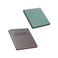
EP2S130F1020I5N Altera, EP2S130F1020I5N Datasheet - Page 30

EP2S130F1020I5N
Manufacturer Part Number
EP2S130F1020I5N
Description
Manufacturer
Altera
Datasheet
1.EP2S130F1020I5N.pdf
(238 pages)
Specifications of EP2S130F1020I5N
Family Name
Stratix II
Number Of Logic Blocks/elements
132540
# I/os (max)
742
Frequency (max)
609.76MHz
Process Technology
90nm (CMOS)
Operating Supply Voltage (typ)
1.2V
Logic Cells
132540
Ram Bits
6747840
Operating Supply Voltage (min)
1.15V
Operating Supply Voltage (max)
1.25V
Operating Temp Range
-40C to 100C
Operating Temperature Classification
Industrial
Mounting
Surface Mount
Pin Count
1020
Package Type
FC-FBGA
Lead Free Status / Rohs Status
Compliant
Available stocks
Company
Part Number
Manufacturer
Quantity
Price
Company:
Part Number:
EP2S130F1020I5N
Manufacturer:
ALTERA
Quantity:
215
Part Number:
EP2S130F1020I5N
Manufacturer:
ALTERA/阿尔特拉
Quantity:
20 000
- Current page: 30 of 238
- Download datasheet (3Mb)
MultiTrack Interconnect
MultiTrack
Interconnect
2–22
Stratix II Device Handbook, Volume 1
Clear & Preset Logic Control
LAB-wide signals control the logic for the register's clear and load/preset
signals. The ALM directly supports an asynchronous clear and preset
function. The register preset is achieved through the asynchronous load
of a logic high. The direct asynchronous preset does not require a NOT-
gate push-back technique. Stratix II devices support simultaneous
asynchronous load/preset, and clear signals. An asynchronous clear
signal takes precedence if both signals are asserted simultaneously. Each
LAB supports up to two clears and one load/preset signal.
In addition to the clear and load/preset ports, Stratix II devices provide a
device-wide reset pin (DEV_CLRn) that resets all registers in the device.
An option set before compilation in the Quartus II software controls this
pin. This device-wide reset overrides all other control signals.
In the Stratix II architecture, connections between ALMs, TriMatrix
memory, DSP blocks, and device I/O pins are provided by the MultiTrack
interconnect structure with DirectDrive
interconnect consists of continuous, performance-optimized routing lines
of different lengths and speeds used for inter- and intra-design block
connectivity. The Quartus II Compiler automatically places critical design
paths on faster interconnects to improve design performance.
DirectDrive technology is a deterministic routing technology that ensures
identical routing resource usage for any function regardless of placement
in the device. The MultiTrack interconnect and DirectDrive technology
simplify the integration stage of block-based designing by eliminating the
re-optimization cycles that typically follow design changes and
additions.
The MultiTrack interconnect consists of row and column interconnects
that span fixed distances. A routing structure with fixed length resources
for all devices allows predictable and repeatable performance when
migrating through different device densities. Dedicated row
interconnects route signals to and from LABs, DSP blocks, and TriMatrix
memory in the same row. These row resources include:
■
■
■
Direct link interconnects between LABs and adjacent blocks
R4 interconnects traversing four blocks to the right or left
R24 row interconnects for high-speed access across the length of the
device
TM
technology. The MultiTrack
Altera Corporation
May 2007
Related parts for EP2S130F1020I5N
Image
Part Number
Description
Manufacturer
Datasheet
Request
R

Part Number:
Description:
CYCLONE II STARTER KIT EP2C20N
Manufacturer:
Altera
Datasheet:

Part Number:
Description:
CPLD, EP610 Family, ECMOS Process, 300 Gates, 16 Macro Cells, 16 Reg., 16 User I/Os, 5V Supply, 35 Speed Grade, 24DIP
Manufacturer:
Altera Corporation
Datasheet:

Part Number:
Description:
CPLD, EP610 Family, ECMOS Process, 300 Gates, 16 Macro Cells, 16 Reg., 16 User I/Os, 5V Supply, 15 Speed Grade, 24DIP
Manufacturer:
Altera Corporation
Datasheet:

Part Number:
Description:
Manufacturer:
Altera Corporation
Datasheet:

Part Number:
Description:
CPLD, EP610 Family, ECMOS Process, 300 Gates, 16 Macro Cells, 16 Reg., 16 User I/Os, 5V Supply, 30 Speed Grade, 24DIP
Manufacturer:
Altera Corporation
Datasheet:

Part Number:
Description:
High-performance, low-power erasable programmable logic devices with 8 macrocells, 10ns
Manufacturer:
Altera Corporation
Datasheet:

Part Number:
Description:
High-performance, low-power erasable programmable logic devices with 8 macrocells, 7ns
Manufacturer:
Altera Corporation
Datasheet:

Part Number:
Description:
Classic EPLD
Manufacturer:
Altera Corporation
Datasheet:

Part Number:
Description:
High-performance, low-power erasable programmable logic devices with 8 macrocells, 10ns
Manufacturer:
Altera Corporation
Datasheet:

Part Number:
Description:
Manufacturer:
Altera Corporation
Datasheet:

Part Number:
Description:
Manufacturer:
Altera Corporation
Datasheet:

Part Number:
Description:
Manufacturer:
Altera Corporation
Datasheet:

Part Number:
Description:
CPLD, EP610 Family, ECMOS Process, 300 Gates, 16 Macro Cells, 16 Reg., 16 User I/Os, 5V Supply, 25 Speed Grade, 24DIP
Manufacturer:
Altera Corporation
Datasheet:


