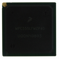
MPC555LFMZP40 Freescale Semiconductor, MPC555LFMZP40 Datasheet - Page 303

MPC555LFMZP40
Manufacturer Part Number
MPC555LFMZP40
Description
IC MCU 32BIT 40MHZ 272-BGA
Manufacturer
Freescale Semiconductor
Series
MPC5xxr
Datasheets
1.MPC555LFMZP40.pdf
(12 pages)
2.MPC555LFMZP40.pdf
(966 pages)
3.MPC555LFMZP40.pdf
(3 pages)
Specifications of MPC555LFMZP40
Core Processor
PowerPC
Core Size
32-Bit
Speed
40MHz
Connectivity
CAN, EBI/EMI, SCI, SPI, UART/USART
Peripherals
POR, PWM, WDT
Number Of I /o
101
Program Memory Size
448KB (448K x 8)
Program Memory Type
FLASH
Ram Size
26K x 8
Voltage - Supply (vcc/vdd)
2.5 V ~ 2.7 V
Data Converters
A/D 32x10b
Oscillator Type
External
Operating Temperature
-40°C ~ 125°C
Package / Case
272-PBGA
Controller Family/series
POWER 5xx
Ram Memory Size
26KB
Cpu Speed
63MIPS
Embedded Interface Type
QSPI, SCI, TouCAN
Operating Temperature Range
-40°C To +125°C
No. Of Pins
272
Rohs Compliant
No
Processor Series
MPC5xx
Core
PowerPC
Data Bus Width
32 bit
Data Ram Size
26 KB
Interface Type
CAN, QSPI, SCI
Maximum Clock Frequency
40 MHz
Number Of Programmable I/os
101
Operating Supply Voltage
3.3 V to 5 V
Maximum Operating Temperature
+ 125 C
Mounting Style
SMD/SMT
Development Tools By Supplier
MPC555CMEE
Minimum Operating Temperature
- 85 C
On-chip Adc
10 bit, 32 Channel
Cpu Family
MPC55xx
Device Core
PowerPC
Device Core Size
32b
Frequency (max)
40MHz
Total Internal Ram Size
32KB
# I/os (max)
101
Operating Supply Voltage (typ)
5V
Instruction Set Architecture
RISC
Operating Temp Range
-40C to 85C
Operating Temperature Classification
Industrial
Mounting
Surface Mount
Pin Count
272
Package Type
BGA
For Use With
MPC555CMEE - KIT EVAL FOR MPC555
Lead Free Status / RoHS Status
Contains lead / RoHS non-compliant
Eeprom Size
-
Lead Free Status / Rohs Status
No
Available stocks
Company
Part Number
Manufacturer
Quantity
Price
Company:
Part Number:
MPC555LFMZP40
Manufacturer:
MOTOLOLA
Quantity:
853
Company:
Part Number:
MPC555LFMZP40
Manufacturer:
Freescale Semiconductor
Quantity:
10 000
Company:
Part Number:
MPC555LFMZP40R2
Manufacturer:
Freescale Semiconductor
Quantity:
10 000
- Current page: 303 of 966
- Download datasheet (15Mb)
9.5 Bus Operations
MPC555
USER’S MANUAL
This section provides a functional description of the system bus, the signals that con-
trol it, and the bus cycles provided for data transfer operations. It also describes the
error conditions, bus arbitration, and reset operation.
The MPC555 / MPC556 generates a system clock output (CLKOUT). This output sets
the frequency of operation for the bus interface directly. Internally, the MPC555 /
MPC556 uses a phase-lock loop (PLL) circuit to generate a master clock for all of the
CPU circuitry (including the bus interface) which is phase-locked to the CLKOUT out-
put signal.
All signals for the MPC555 / MPC556 bus interface are specified with respect to the
rising edge of the external CLKOUT and are guaranteed to be sampled as inputs or
changed as outputs with respect to that edge. Since the same clock edge is referenced
for driving or sampling the bus signals, the possibility of clock skew could exist be-
tween various modules in a system due to routing or the use of multiple clock lines. It
Signal Name
Bus request
Bus grant
Bus busy
/
MPC556
BR
BG
BB
Table 9-1 MPC555 / MPC556 SIU Signals (Continued)
Freescale Semiconductor, Inc.
Pins
1
1
1
For More Information On This Product,
EXTERNAL BUS INTERFACE
Active
Go to: www.freescale.com
Low
Low
Low
Rev. 15 October 2000
ARBITRATION
I/O
O
O
O
I
I
I
When the internal arbiter is enabled, BR assertion in-
dicates that an external master is requesting the bus.
Driven by the MPC555 / MPC556 when the internal
arbiter is disabled and the chip is not parked.
When the internal arbiter is enabled, the MPC555 /
MPC556 asserts this signal to indicate that an exter-
nal master may assume ownership of the bus and be-
gin a bus transaction. The BG signal should be
qualified by the master requesting the bus in order to
ensure it is the bus owner:
Qualified bus grant = BG & ~ BB
When the internal arbiter is disabled, BG is sampled
and properly qualified by the MPC555 / MPC556
when an external bus transaction is to be executed by
the chip.
When the internal arbiter is enabled, the MPC555 /
MPC556 asserts this signal to indicate that it is the
current owner of the bus.
When the internal arbiter is disabled, the MPC555 /
MPC556 asserts this signal after the external arbiter
has granted the ownership of the bus to the chip and
it is ready to start the transaction.
When the internal arbiter is enabled, the MPC555 /
MPC556 samples this signal to get indication of when
the external master ended its bus tenure (BB negat-
ed).
When the internal arbiter is disabled, the BB is sam-
pled to properly qualify the BG line when an external
bus transaction is to be executed by the chip.
Description
MOTOROLA
9-7
Related parts for MPC555LFMZP40
Image
Part Number
Description
Manufacturer
Datasheet
Request
R
Part Number:
Description:
Manufacturer:
Freescale Semiconductor, Inc
Datasheet:
Part Number:
Description:
Manufacturer:
Freescale Semiconductor, Inc
Datasheet:
Part Number:
Description:
Manufacturer:
Freescale Semiconductor, Inc
Datasheet:
Part Number:
Description:
Manufacturer:
Freescale Semiconductor, Inc
Datasheet:
Part Number:
Description:
Manufacturer:
Freescale Semiconductor, Inc
Datasheet:
Part Number:
Description:
Manufacturer:
Freescale Semiconductor, Inc
Datasheet:
Part Number:
Description:
Manufacturer:
Freescale Semiconductor, Inc
Datasheet:
Part Number:
Description:
Manufacturer:
Freescale Semiconductor, Inc
Datasheet:
Part Number:
Description:
Manufacturer:
Freescale Semiconductor, Inc
Datasheet:
Part Number:
Description:
Manufacturer:
Freescale Semiconductor, Inc
Datasheet:
Part Number:
Description:
Manufacturer:
Freescale Semiconductor, Inc
Datasheet:
Part Number:
Description:
Manufacturer:
Freescale Semiconductor, Inc
Datasheet:
Part Number:
Description:
Manufacturer:
Freescale Semiconductor, Inc
Datasheet:
Part Number:
Description:
Manufacturer:
Freescale Semiconductor, Inc
Datasheet:
Part Number:
Description:
Manufacturer:
Freescale Semiconductor, Inc
Datasheet:


