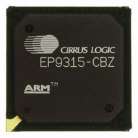
EP9315-CBZ Cirrus Logic Inc, EP9315-CBZ Datasheet - Page 20

EP9315-CBZ
Manufacturer Part Number
EP9315-CBZ
Description
IC ARM9 SOC ENH UNIV 352PBGA
Manufacturer
Cirrus Logic Inc
Series
EP9r
Specifications of EP9315-CBZ
Core Size
16/32-Bit
Core Processor
ARM9
Speed
200MHz
Connectivity
EBI/EMI, EIDE, Ethernet, I²C, IrDA, Keypad/Touchscreen, PCMCIA, SPI, UART/USART, USB
Peripherals
AC'97, DMA, I²:S, LCD, LED, MaverickKey, POR, PWM, WDT
Number Of I /o
16
Program Memory Type
ROMless
Ram Size
32K x 8
Voltage - Supply (vcc/vdd)
1.65 V ~ 3.6 V
Data Converters
A/D 8x12b
Oscillator Type
External
Operating Temperature
0°C ~ 70°C
Package / Case
352-BGA
Controller Family/series
(ARM9)
No. Of I/o's
16
Cpu Speed
200MHz
No. Of Timers
5
Digital Ic Case Style
BGA
Supply Voltage Range
1.65V To 1.94V, 3V To 3.6V
Embedded Interface Type
SPI
Rohs Compliant
Yes
Processor Series
EP93xx
Core
ARM920T
Data Bus Width
32 bit
3rd Party Development Tools
MDK-ARM, RL-ARM, ULINK2
Development Tools By Supplier
EDB9315A-Z
Case
BGA
Dc
06+
Lead Free Status / RoHS Status
Lead free / RoHS Compliant
For Use With
598-1144 - KIT DEVELOPMENT EP9315 ARM9
Eeprom Size
-
Program Memory Size
-
Lead Free Status / Rohs Status
Details
Other names
598-1139
Available stocks
Company
Part Number
Manufacturer
Quantity
Price
Part Number:
EP9315-CBZ
Manufacturer:
CIRRUS
Quantity:
20 000
- Current page: 20 of 824
- Download datasheet (13Mb)
EP93xx User’s Guide
xx
Table 11-1. Frame Bandwidth Allocation ....................................................................................................11-7
Table 11-2. OpenHCI Register Addresses................................................................................................11-11
Table 12-1. PCMCIA Address Memory Ranges..........................................................................................12-5
Table 12-2. PCMCIA Pin Usage..................................................................................................................12-5
Table 12-3. Supported 8-Bit Accesses........................................................................................................12-8
Table 12-4. Supported 16-Bit Accesses......................................................................................................12-8
Table 12-5. PCMCIA Legacy Usage ...........................................................................................................12-8
Table 12-6. Accesses to 8-Bit Attribute / Common / IO Memory.................................................................12-9
Table 12-7. Accesses to 16-Bit Attribute / Common / IO Memory...............................................................12-9
Table 12-8. Static Memory Controller (SMC) Register Map......................................................................12-10
Table 13-1. Boot Device Selection ..............................................................................................................13-2
Table 13-2. Address Decoding for Synchronous Memory Domains ...........................................................13-3
Table 13-3. Synchronous Memory Address Decoding................................................................................13-4
Table 13-4. General SDRAM Initialization Sequence .................................................................................13-4
Table 13-5. Mode Register Command Decoding for 32-bit Wide Memory Bus ..........................................13-6
Table 13-6. Sync Memory CAS...................................................................................................................13-7
Table 13-7. Sync Memory RAS, Burst Type, and Write Burst Length.........................................................13-7
Table 13-8. Burst Length.............................................................................................................................13-7
Table 13-9. Chip Select Decoding...............................................................................................................13-9
Table 13-10. Memory Addressing Example ..............................................................................................13-11
Table 13-11. EP93xx SDRAM Address Ranges (16-Bit Wide Data Systems)..........................................13-12
Table 13-12. Address Bits Used for Chip Select .......................................................................................13-17
Table 13-13. Synchronous Memory Controller Registers .........................................................................13-17
Table 13-14. Synchronous Memory Command Encoding.........................................................................13-20
Table 14-1. Receive FIFO Bit Functions .....................................................................................................14-6
Table 14-2. Legal HDLC Mode Configurations .........................................................................................14-10
Table 14-3. HDLC Receive Address Matching Modes..............................................................................14-13
Table 14-4. UART1 Pin Functionality ........................................................................................................14-15
Table 14-5. DeviceCfg Register Bit Functions ..........................................................................................14-15
Table 15-1. UART2 / IrDA Modes ...............................................................................................................15-5
Table 15-2. IonU2 Pin Function...................................................................................................................15-5
Table 16-1. UART3 Pin Functionality ..........................................................................................................16-1
Table 16-2. DeviceCfg Register Bit Functions ............................................................................................16-2
Table 17-1. Bit Values to Select Ir Module ..................................................................................................17-3
Table 17-2. Address Offsets for End-of-Frame Data...................................................................................17-5
Table 17-3. MIR Frame Format...................................................................................................................17-9
Table 17-4. DeviceCfg.IonU2 Pin Function ...............................................................................................17-20
©
Copyright 2007 Cirrus Logic, Inc.
DS785UM1
Related parts for EP9315-CBZ
Image
Part Number
Description
Manufacturer
Datasheet
Request
R

Part Number:
Description:
IC ARM920T MCU 200MHZ 352-PBGA
Manufacturer:
Cirrus Logic Inc
Datasheet:

Part Number:
Description:
32-Bit Microcontroller IC
Manufacturer:
Cirrus Logic Inc
Datasheet:

Part Number:
Description:
IC ARM920T MCU 200MHZ 352-PBGA
Manufacturer:
Cirrus Logic Inc
Datasheet:

Part Number:
Description:
MCU, MPU & DSP Development Tools Eval Bd Uni. ARM9 SOC Processor
Manufacturer:
Cirrus Logic Inc
Datasheet:

Part Number:
Description:
Development Kit
Manufacturer:
Cirrus Logic Inc
Datasheet:

Part Number:
Description:
Development Kit
Manufacturer:
Cirrus Logic Inc
Datasheet:

Part Number:
Description:
High-efficiency PFC + Fluorescent Lamp Driver Reference Design
Manufacturer:
Cirrus Logic Inc
Datasheet:

Part Number:
Description:
Development Kit
Manufacturer:
Cirrus Logic Inc
Datasheet:

Part Number:
Description:
Development Kit
Manufacturer:
Cirrus Logic Inc
Datasheet:

Part Number:
Description:
Development Kit
Manufacturer:
Cirrus Logic Inc
Datasheet:

Part Number:
Description:
Development Kit
Manufacturer:
Cirrus Logic Inc
Datasheet:

Part Number:
Description:
Development Kit
Manufacturer:
Cirrus Logic Inc
Datasheet:

Part Number:
Description:
Development Kit
Manufacturer:
Cirrus Logic Inc
Datasheet:

Part Number:
Description:
Ref Bd For Speakerbar MSA & DSP Products
Manufacturer:
Cirrus Logic Inc


