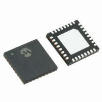
MRF89XA-I/MQ Microchip Technology, MRF89XA-I/MQ Datasheet - Page 100

MRF89XA-I/MQ
Manufacturer Part Number
MRF89XA-I/MQ
Description
TXRX ISM SUB-GHZ ULP 32QFN
Manufacturer
Microchip Technology
Specifications of MRF89XA-I/MQ
Package / Case
32-WFQFN Exposed Pad
Frequency
863MHz ~ 870MHz, 902MHz ~ 928MHz, 950MHz ~ 960MHz
Data Rate - Maximum
200kbps
Modulation Or Protocol
FSK, OOK
Applications
ISM
Power - Output
12.5dBm
Sensitivity
-113dBm
Voltage - Supply
2.1 V ~ 3.6 V
Current - Receiving
3mA
Current - Transmitting
25mA
Data Interface
PCB, Surface Mount
Antenna Connector
PCB, Surface Mount
Operating Temperature
-40°C ~ 85°C
Number Of Receivers
1
Number Of Transmitters
1
Wireless Frequency
863 MHz to 870 MHz, 902 MHz to 928 MHz, 950 MHz to 960 MHz
Interface Type
SPI
Noise Figure
- 112 dBc
Output Power
- 8.5 dBm, + 12.5 dBm
Operating Supply Voltage
2.1 V to 3.6 V
Maximum Operating Temperature
+ 85 C
Mounting Style
SMD/SMT
Maximum Data Rate
256 Kbps
Maximum Supply Current
25 mA
Minimum Operating Temperature
- 40 C
Modulation
FSK
Lead Free Status / RoHS Status
Lead free / RoHS Compliant
Memory Size
-
Lead Free Status / Rohs Status
Lead free / RoHS Compliant
Available stocks
Company
Part Number
Manufacturer
Quantity
Price
Company:
Part Number:
MRF89XA-I/MQ
Manufacturer:
MICROCHIP
Quantity:
12 000
4.4
The Power Amplifier (PA) integrated in the MRF89XA
operates under a regulated voltage supply of 1.8V. The
external RF choke inductor is biased by an internal reg-
ulator output made available on the PARS pin (pin 29).
These features help PA output power to be consistent
over the power supply range. This is important for
applications that allow predictable RF performance and
battery life.
FIGURE 4-4:
DS70622B-page 100
MRF89XA
Note:
POWER AMPLIFIER
Refer to Section 4.7 “Bill of Materials”
for an optimized PA load setting.
OPTIMAL LOAD IMPEDANCE CHART
Preliminary
4.4.1
As the PA and the LNA front-ends in the MRF89XA
share the same input/output pin, they are internally
matched to approximately 50Ω. Figure 4-4illustrates
optimum load impedance of RFIO through an imped-
ance chart.
Max Power
Zopt = 30 + j25Ω
OPTIMUM LOAD IMPEDANCE
Pmax-1dB circle
© 2010 Microchip Technology Inc.


