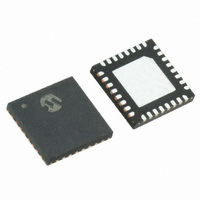
MRF89XA-I/MQ Microchip Technology, MRF89XA-I/MQ Datasheet - Page 83

MRF89XA-I/MQ
Manufacturer Part Number
MRF89XA-I/MQ
Description
TXRX ISM SUB-GHZ ULP 32QFN
Manufacturer
Microchip Technology
Specifications of MRF89XA-I/MQ
Package / Case
32-WFQFN Exposed Pad
Frequency
863MHz ~ 870MHz, 902MHz ~ 928MHz, 950MHz ~ 960MHz
Data Rate - Maximum
200kbps
Modulation Or Protocol
FSK, OOK
Applications
ISM
Power - Output
12.5dBm
Sensitivity
-113dBm
Voltage - Supply
2.1 V ~ 3.6 V
Current - Receiving
3mA
Current - Transmitting
25mA
Data Interface
PCB, Surface Mount
Antenna Connector
PCB, Surface Mount
Operating Temperature
-40°C ~ 85°C
Number Of Receivers
1
Number Of Transmitters
1
Wireless Frequency
863 MHz to 870 MHz, 902 MHz to 928 MHz, 950 MHz to 960 MHz
Interface Type
SPI
Noise Figure
- 112 dBc
Output Power
- 8.5 dBm, + 12.5 dBm
Operating Supply Voltage
2.1 V to 3.6 V
Maximum Operating Temperature
+ 85 C
Mounting Style
SMD/SMT
Maximum Data Rate
256 Kbps
Maximum Supply Current
25 mA
Minimum Operating Temperature
- 40 C
Modulation
FSK
Lead Free Status / RoHS Status
Lead free / RoHS Compliant
Memory Size
-
Lead Free Status / Rohs Status
Lead free / RoHS Compliant
Available stocks
Company
Part Number
Manufacturer
Quantity
Price
Company:
Part Number:
MRF89XA-I/MQ
Manufacturer:
MICROCHIP
Quantity:
12 000
3.10.3
Table 3-8 and Table 3-9 describes the interrupts avail-
able in Buffered mode.
TABLE 3-8:
TABLE 3-9:
3.10.4
Depending
microcontroller connections may not be required:
• IRQ0: if none of the relevant IRQ sources are
• IRQ1: if none of the relevant IRQ sources are
• SDO: if no read register access is needed and the
© 2010 Microchip Technology Inc.
IRQ0RXS<1:0>
00 (default)
01
10
11
IRQ1RXS<1:0>
00 (default)
01
10
11
IRQ0TXST
0 (default)
1
IRQ1TX
0 (default)
1
Interrupt Name
Note:
Interrupt Name
Note:
used. In this case, leave the pin floating.
used. In this case, leave the pin floating.
device is used in TX mode only. In this case, pull
up to V
Note:
DD
INTERRUPT SIGNALS MAPPING
Also refer the DMODE1 and DMODE0 bits in the FTXRXIREG and FTPRIREG registers for details.
Also refer the DMODE1 and DMODE0 bits in the FTXRXIREG and FTPRIREG registers for details.
HOST MICROCONTROLLER
CONNECTIONS IN BUFFERED
MODE
The DATA pin (pin 20), which is unused in
Buffered mode, should be pulled-up to
V
provides details about the MRF89XA pin
configuration and chip mode.
through a 100 kΩ resistor.
DD
on
through a 100 kΩ resistor. Table 2-4,
INTERRUPT MAPPING IN BUFFERED RX AND STAND-BY MODE
INTERRUPT MAPPING IN BUFFERED TX MODE
the
Interrupts
application,
IRQ0
IRQ0
IRQ0
IRQ0
IRQ1
IRQ1
IRQ1
IRQ1
Interrupts
IRQ0
IRQ0
IRQ1
IRQ1
some
Data Mode
Buffered
Buffered
Buffered
Buffered
Buffered
Buffered
Buffered
Buffered
host
Preliminary
Data Mode
Buffered
Buffered
Buffered
Buffered
Interrupt Type
Output
Output
Output
Output
Output
Output
Output
Output
FIGURE 3-24:
3.10.5
The data processing related registers are appropriately
configured as listed in Table 3-10. In this example we
assume Sync word recognition is on and FIFOFM = 0.
MRF89XA
Interrupt Type
FIFO_THRESHOLD FIFO_THRESHOLD
BUFFERED MODE EXAMPLE
Output
Output
Output
Output
CSCON
CSDAT
WRITEBYTE
RX Interrupt
FIFOEMPTY
Sync Pattern
FIFOFULL
IRQ0
IRQ1
SDO
SCK
Source
SDI
RSSI
—
—
HOST MCU
CONNECTIONS IN
BUFFERED MODE
MRF89XA
Interrupt Source
Stand-by Interrupt
MIcrocontroller
FIFOEMPTY
FIFOEMPTY
FIFOFULL
DS70622B-page 83
FIFOEMPTY
TXDONE
FIFOFULL
PIC
Source
®
—
—
—
—
—


