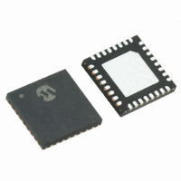
MRF89XA-I/MQ Microchip Technology, MRF89XA-I/MQ Datasheet - Page 85

MRF89XA-I/MQ
Manufacturer Part Number
MRF89XA-I/MQ
Description
TXRX ISM SUB-GHZ ULP 32QFN
Manufacturer
Microchip Technology
Specifications of MRF89XA-I/MQ
Package / Case
32-WFQFN Exposed Pad
Frequency
863MHz ~ 870MHz, 902MHz ~ 928MHz, 950MHz ~ 960MHz
Data Rate - Maximum
200kbps
Modulation Or Protocol
FSK, OOK
Applications
ISM
Power - Output
12.5dBm
Sensitivity
-113dBm
Voltage - Supply
2.1 V ~ 3.6 V
Current - Receiving
3mA
Current - Transmitting
25mA
Data Interface
PCB, Surface Mount
Antenna Connector
PCB, Surface Mount
Operating Temperature
-40°C ~ 85°C
Number Of Receivers
1
Number Of Transmitters
1
Wireless Frequency
863 MHz to 870 MHz, 902 MHz to 928 MHz, 950 MHz to 960 MHz
Interface Type
SPI
Noise Figure
- 112 dBc
Output Power
- 8.5 dBm, + 12.5 dBm
Operating Supply Voltage
2.1 V to 3.6 V
Maximum Operating Temperature
+ 85 C
Mounting Style
SMD/SMT
Maximum Data Rate
256 Kbps
Maximum Supply Current
25 mA
Minimum Operating Temperature
- 40 C
Modulation
FSK
Lead Free Status / RoHS Status
Lead free / RoHS Compliant
Memory Size
-
Lead Free Status / Rohs Status
Lead free / RoHS Compliant
Available stocks
Company
Part Number
Manufacturer
Quantity
Price
Company:
Part Number:
MRF89XA-I/MQ
Manufacturer:
MICROCHIP
Quantity:
12 000
3.11
Similar to Buffered mode operation, in Packet mode the
NRZ data to/from the (de)modulator is not directly
accessed by the host microcontroller but is stored in
the FIFO and accessed through the SPI data interface.
The MRF89XA’s packet handler also performs several
packet oriented tasks such as Preamble and Sync
word generation, CRC calculation/check, DC scram-
bling
filtering. This simplifies the software still further and
reduces microcontroller overhead by performing these
repetitive tasks within the MRF89XA itself.
FIGURE 3-25:
© 2010 Microchip Technology Inc.
Data
(whitening/dewhitening
Packet Mode
Datapath
TX
RX
RECOG.
SYNC
PACKET MODE BLOCK DIAGRAM
of
HANDLER
PACKET
data),
MRF89XA
address
Preliminary
CONTROL
(+SR)
FIFO
Another important feature is the ability to fill and empty
the FIFO in Stand-by mode, ensuring optimum power
consumption and adding more flexibility for the soft-
ware. Figure 3-25 shows the interface diagram during
Packet Mode.
Note:
Bit Synchronizer and Sync word recogni-
tion are automatically enabled in Packet
mode.
CONFIG
DATA
SPI
MRF89XA
DS70622B-page 85
/CSCON
SCK
SDI
SDO
CSDAT
IRQ1
IRQ0


