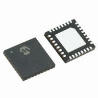
MRF89XA-I/MQ Microchip Technology, MRF89XA-I/MQ Datasheet - Page 32

MRF89XA-I/MQ
Manufacturer Part Number
MRF89XA-I/MQ
Description
TXRX ISM SUB-GHZ ULP 32QFN
Manufacturer
Microchip Technology
Specifications of MRF89XA-I/MQ
Package / Case
32-WFQFN Exposed Pad
Frequency
863MHz ~ 870MHz, 902MHz ~ 928MHz, 950MHz ~ 960MHz
Data Rate - Maximum
200kbps
Modulation Or Protocol
FSK, OOK
Applications
ISM
Power - Output
12.5dBm
Sensitivity
-113dBm
Voltage - Supply
2.1 V ~ 3.6 V
Current - Receiving
3mA
Current - Transmitting
25mA
Data Interface
PCB, Surface Mount
Antenna Connector
PCB, Surface Mount
Operating Temperature
-40°C ~ 85°C
Number Of Receivers
1
Number Of Transmitters
1
Wireless Frequency
863 MHz to 870 MHz, 902 MHz to 928 MHz, 950 MHz to 960 MHz
Interface Type
SPI
Noise Figure
- 112 dBc
Output Power
- 8.5 dBm, + 12.5 dBm
Operating Supply Voltage
2.1 V to 3.6 V
Maximum Operating Temperature
+ 85 C
Mounting Style
SMD/SMT
Maximum Data Rate
256 Kbps
Maximum Supply Current
25 mA
Minimum Operating Temperature
- 40 C
Modulation
FSK
Lead Free Status / RoHS Status
Lead free / RoHS Compliant
Memory Size
-
Lead Free Status / Rohs Status
Lead free / RoHS Compliant
Available stocks
Company
Part Number
Manufacturer
Quantity
Price
Company:
Part Number:
MRF89XA-I/MQ
Manufacturer:
MICROCHIP
Quantity:
12 000
2.14
2.14.1
REGISTER 2-1:
DS70622B-page 32
MRF89XA
bit 7
R = Readable bit
-n = Value at POR
r = Reserved
bit 7-5
bit 4-3
bit 2-1
bit 0
R/W-0
General Configuration Registers
GENERAL CONFIGURATION
REGISTER DETAILS
CMOD<2:0>: Chip Mode bits
These bits select the mode of operation of the transceiver.
111 = Reserved; do not use
110 = Reserved; do not use
101 = Reserved; do not use
100 = Transmit mode
011 = Receive mode
010 = Frequency Synthesizer mode
001 = Stand-by mode (default)
000 = Sleep mode
FBS<1:0>: Frequency Band Select bits
These bits set the frequency band to be used in Sub-GHz range.
11 = Reserved
10 = 950-960 MHz or 863- 870 MHz (application circuit dependant)
01 = 915-928 MHz (default)
00 = 902-915 MHz
VCOT<1:0>: TX bits
For each AFC cycle run, these bits will toggle between logic ‘1’ and logic ‘0’.
11 = Vtune + 180 mV typ
10 = Vtune + 120 mV typ
01 = Vtune + 60 mV typ
00 = Vtune determined by tank inductors values (default)
RPS: RPS Select bit
This bit selects between the two sets of frequency dividers of the PLL, Ri/Pi/Si. For more information,
see Section 3.2.7 “Frequency Calculation”.
1 = Enable R2/P2/S2 set
0 = Enable R1/P1/S1 set (default)
CMOD<2:0>
R/W-0
GCONREG: GENERAL CONFIGURATION REGISTER
(ADDRESS:0X00) (POR:0X28)
W = Writable bit
‘1’ = Bit is set
R/W-1
R/W-0
Preliminary
FBS<1:0>
U = Unimplemented bit, read as ‘0’
‘0’ = Bit is cleared
R/W-1
R/W-0
VCOT<1:0>
© 2010 Microchip Technology Inc.
x = Bit is unknown
R/W-0
R/W-0
RPS
bit 0


