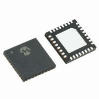
MRF89XA-I/MQ Microchip Technology, MRF89XA-I/MQ Datasheet - Page 65

MRF89XA-I/MQ
Manufacturer Part Number
MRF89XA-I/MQ
Description
TXRX ISM SUB-GHZ ULP 32QFN
Manufacturer
Microchip Technology
Specifications of MRF89XA-I/MQ
Package / Case
32-WFQFN Exposed Pad
Frequency
863MHz ~ 870MHz, 902MHz ~ 928MHz, 950MHz ~ 960MHz
Data Rate - Maximum
200kbps
Modulation Or Protocol
FSK, OOK
Applications
ISM
Power - Output
12.5dBm
Sensitivity
-113dBm
Voltage - Supply
2.1 V ~ 3.6 V
Current - Receiving
3mA
Current - Transmitting
25mA
Data Interface
PCB, Surface Mount
Antenna Connector
PCB, Surface Mount
Operating Temperature
-40°C ~ 85°C
Number Of Receivers
1
Number Of Transmitters
1
Wireless Frequency
863 MHz to 870 MHz, 902 MHz to 928 MHz, 950 MHz to 960 MHz
Interface Type
SPI
Noise Figure
- 112 dBc
Output Power
- 8.5 dBm, + 12.5 dBm
Operating Supply Voltage
2.1 V to 3.6 V
Maximum Operating Temperature
+ 85 C
Mounting Style
SMD/SMT
Maximum Data Rate
256 Kbps
Maximum Supply Current
25 mA
Minimum Operating Temperature
- 40 C
Modulation
FSK
Lead Free Status / RoHS Status
Lead free / RoHS Compliant
Memory Size
-
Lead Free Status / Rohs Status
Lead free / RoHS Compliant
Available stocks
Company
Part Number
Manufacturer
Quantity
Price
Company:
Part Number:
MRF89XA-I/MQ
Manufacturer:
MICROCHIP
Quantity:
12 000
3.4
The MRF89XA is set to Receive mode when the
CMOD<2:0> bits (GCONREG<7:5>) are set to ‘011’
(see Register 2-1).
The receiver is based on the superheterodyne
architecture. The front-end is composed of an LNA and
a mixer whose gains are constant. The mixer
down-converts the RF signal to an intermediate
frequency, which is equal to one-eighth of the LO
frequency, which in turn is equal to eight-ninths of the
RF frequency. Behind this first mixer there is a variable
gain IF amplifier that can be programmed from
maximum gain to 13.5 dB in 4.5 dB steps with the
IFGAIN<1:0> bits (DMODREG<1:0>).
After the variable gain IF amplifier, the signal is
down-converted into two I and Q base-band signals by
two quadrature mixers that are fed by reference signals
at one-eighth the LO frequency. These I and Q signals
are then filtered and amplified before demodulation.
The first filter is a second-order passive R-C filter
whose bandwidth can be programmed to 16 values
with the PASFILV<3:0> bits (FILCREG<7:4>).
The second filter can be configured as either a
third-order Butterworth active filter, which acts as a
low-pass filter for the zero-IF FSK configuration, or as
a polyphase band-pass filter for the low-IF OOK
configuration. To select Butterworth low-pass filter
operation, the POLFILEN bit (SYNCREG<7>) is set to
‘0’.
The bandwidth of the Butterworth filter can be
programmed to 16 values by configuring the
BUTFILV<3:0> bits (FILCREG<3:0>). The low-IF
configuration must be used for OOK modulation. This
configuration is enabled when the POLFILEN bit
(SYNCREG<7>) is set to ‘1’.
The center frequency of the polyphase filter can be
programmed to 16 values by setting the POLCFV<3:0>
bits (PFCREG<7:4>). The bandwidth of the filter can be
programmed by configuring the BUTFILV<3:0> bits
(FILCREG<3:0>). In OOK mode, the value of the
low-IF is equal to the deviation frequency defined in
FDEVREG.
In addition to the channel filtering, the function of the
polyphase filter is to reject the image. Figure 3-5
illustrates the two configurations of the second IF filter.
In the Butterworth configuration, F
cut-off frequency. In
configuration, F
the POLCFV<3:0> bits (PFCREG<7:4>), and F
the upper 3 dB bandwidth of the filter whose offset,
referenced to F
(FILCREG<3:0>).
© 2010 Microchip Technology Inc.
Receiver
OPP
OPP
, is given by BUTFILV<3:0> bits
is the center frequency given by
the polyphase
CBW
is the 3 dB
band-pass
CPP
Preliminary
is
3.4.1
FIGURE 3-5:
After filtering, the I and Q signals are each amplified by
a chain of 11 amplifiers having 6 dB of gain each. The
outputs of these amplifiers and their intermediate 3 dB
nodes are used to evaluate the received signal strength
(RSSI). Limiters are located behind the 11 amplifiers of
the I and Q chains and the signals at the output of these
limiters are used by the FSK demodulator. The RSSI
output is used by the OOK demodulator. The global
bandwidth of the entire base-band chain is given by the
bandwidths of the passive filter, the Butterworth filter,
the amplifier chain, and the limiter. The maximum
achievable global bandwidth when the bandwidths of
the first three blocks are programmed at their upper
limit is approximately 350 kHz.
3.4.2
In Receive mode, the RFIO pin is connected to a fixed
gain, common-gate, Low Noise Amplifier (LNA). The
performance of this amplifier is such that the Noise
Figure (NF) of the receiver is estimated to be
approximately 7 dB.
3.4.3
Following the LNA and first down-conversion, there is
an IF amplifier whose gain can be programmed from
-13.5 dB to 0 dB in 4.5 dB steps, through the
IFGAIN<1:0> bits (DMODREG<1:0>). The default
setting corresponds to 0 dB gain, but lower values can
be used to increase the RSSI dynamic range. For more
information, refer Section 3.4.7 “received signal
strength (RSSI)”.
Polyphase Band-Pass Filter for OOK
Butterworth Low-Pass Filter for FSK
MRF89XA SECOND IF FILTER
DETAILS
2 * F
LNA AND FIRST MIXER
IF GAIN AND SECOND I/Q MIXER
OPP
– F
IF FILTERS IN FSK AND
OOK MODES
CPP
FCBW
F
MRF89XA
OPP
DS70622B-page 65
F
CPP


