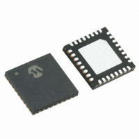
MRF89XA-I/MQ Microchip Technology, MRF89XA-I/MQ Datasheet - Page 63

MRF89XA-I/MQ
Manufacturer Part Number
MRF89XA-I/MQ
Description
TXRX ISM SUB-GHZ ULP 32QFN
Manufacturer
Microchip Technology
Specifications of MRF89XA-I/MQ
Package / Case
32-WFQFN Exposed Pad
Frequency
863MHz ~ 870MHz, 902MHz ~ 928MHz, 950MHz ~ 960MHz
Data Rate - Maximum
200kbps
Modulation Or Protocol
FSK, OOK
Applications
ISM
Power - Output
12.5dBm
Sensitivity
-113dBm
Voltage - Supply
2.1 V ~ 3.6 V
Current - Receiving
3mA
Current - Transmitting
25mA
Data Interface
PCB, Surface Mount
Antenna Connector
PCB, Surface Mount
Operating Temperature
-40°C ~ 85°C
Number Of Receivers
1
Number Of Transmitters
1
Wireless Frequency
863 MHz to 870 MHz, 902 MHz to 928 MHz, 950 MHz to 960 MHz
Interface Type
SPI
Noise Figure
- 112 dBc
Output Power
- 8.5 dBm, + 12.5 dBm
Operating Supply Voltage
2.1 V to 3.6 V
Maximum Operating Temperature
+ 85 C
Mounting Style
SMD/SMT
Maximum Data Rate
256 Kbps
Maximum Supply Current
25 mA
Minimum Operating Temperature
- 40 C
Modulation
FSK
Lead Free Status / RoHS Status
Lead free / RoHS Compliant
Memory Size
-
Lead Free Status / Rohs Status
Lead free / RoHS Compliant
Available stocks
Company
Part Number
Manufacturer
Quantity
Price
Company:
Part Number:
MRF89XA-I/MQ
Manufacturer:
MICROCHIP
Quantity:
12 000
3.3
The MRF89XA is set to Transmit mode when the
CMOD<2:0> bits (GCONREG<7:5>) are set to ‘100’
(see Register 2-1).
The transmitter chain in the MRF89XA is based on the
same double-conversion architecture and uses the
same intermediate frequencies as the receiver chain.
The frequency synthesizer is based on an integer-N
type PLL, having bandwidth of 15k Hz. Two
programmable frequency dividers in the feedback loop
of the PLL and one programmable divider on the
reference oscillator allow the LO frequency to be
adjusted. The reference frequency is generated by a
crystal oscillator running at 12.8 MHz.
3.3.1
In Continuous Transmit mode, setting the bit rate
through the BRVAL<6:0> bits (BRSREG<6:0>) is
useful to determine the frequency of DCLK. As
explained in Section 3.9.1 “TX Processing”, DCLK
will trigger an interrupt on the host microcontroller each
time a new bit has to be transmitted, as shown in
Equation 3-4.
EQUATION 3-4:
3.3.2
Bit rate, frequency deviation, and TX interpolation filter
settings are a function of the crystal frequency (f
the reference oscillator. Settings other than those
programmed with a 12.8 MHz crystal can be obtained
by selecting the correct reference oscillator frequency.
3.3.3
The frequency deviation, f
programmed
(FDEVREG<7:0>), as shown in Equation 3-5.
EQUATION 3-5:
For correct operation, the modulation index β should
be equal to Equation 3-6.
EQUATION 3-6:
© 2010 Microchip Technology Inc.
Transmitter
f
BR
dev
BIT RATE SETTING
ALTERNATIVE SETTINGS
f
dev
=
=
SETTING IN FSK MODE
-------------------------------------------------------------------------
64
through
-------------------------------------------------------------------------- -
32
•
•
β
[
[
=
1
1
+
+
2
val BRVAL<6:0>
val FDVAL<7:0>
•
dev
the
f
-------- -
BR
f
dev
(
, of the FSK transmitter is
f
(
xtal
xtal
≥
2
FDVAL<7:0>
)
)
]
]
xtal
Preliminary
bits
) of
For communication between a pair of MRF89XAs the
f
operation on the receiver side.
3.3.4
f
However, due to the DDS baseband signal generation,
the OOK signal is always offset by “-f
Section 3.2.7
suggested that f
in OOK mode.
3.3.5
After digital-to-analog conversion, the I and Q signals
are smoothened by interpolation filters. Low-pass filters
in this block digitally generates the signal and prevent
the alias signals from entering the modulators. Its
bandwidth
TXIPOLFV<6:0> bits (TXPARCREG>7:1), and should
be calculated as shown in Equation 3-7.
EQUATION 3-7:
For most of the applications a BW of around 125 KHz
would
reached. However, the impact on spectral purity will be
negligible due to the existing wideband channel.
dev
dev
modulation, the recommended filter setting cannot be
Where,
as set in FDEVREG
BR is the physical bit rate of transmission
Note:
f
dev
has no physical meaning in OOK Transmit mode.
should be at least 33 kHz to ensure a correct
is the programmed frequency deviation
be
f
INTERPOLATION FILTER
Low interpolation filter bandwidth will
attenuate the baseband I/Q signals, thus
reducing the power of the FSK signal.
Conversely, excessive bandwidth will
degrade spectral purity.
dev
acceptable,
can
SETTING IN OOK MODE
dev
“Frequency
BW
retains its default value of 100 kHz
≅
be
3
•
programmed
but
f
dev
MRF89XA
+
Calculation”).
for
BR
------ -
2
DS70622B-page 63
wideband
with
dev
” (see
It
FSK
the
is


