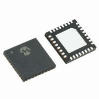
MRF89XA-I/MQ Microchip Technology, MRF89XA-I/MQ Datasheet - Page 88

MRF89XA-I/MQ
Manufacturer Part Number
MRF89XA-I/MQ
Description
TXRX ISM SUB-GHZ ULP 32QFN
Manufacturer
Microchip Technology
Specifications of MRF89XA-I/MQ
Package / Case
32-WFQFN Exposed Pad
Frequency
863MHz ~ 870MHz, 902MHz ~ 928MHz, 950MHz ~ 960MHz
Data Rate - Maximum
200kbps
Modulation Or Protocol
FSK, OOK
Applications
ISM
Power - Output
12.5dBm
Sensitivity
-113dBm
Voltage - Supply
2.1 V ~ 3.6 V
Current - Receiving
3mA
Current - Transmitting
25mA
Data Interface
PCB, Surface Mount
Antenna Connector
PCB, Surface Mount
Operating Temperature
-40°C ~ 85°C
Number Of Receivers
1
Number Of Transmitters
1
Wireless Frequency
863 MHz to 870 MHz, 902 MHz to 928 MHz, 950 MHz to 960 MHz
Interface Type
SPI
Noise Figure
- 112 dBc
Output Power
- 8.5 dBm, + 12.5 dBm
Operating Supply Voltage
2.1 V to 3.6 V
Maximum Operating Temperature
+ 85 C
Mounting Style
SMD/SMT
Maximum Data Rate
256 Kbps
Maximum Supply Current
25 mA
Minimum Operating Temperature
- 40 C
Modulation
FSK
Lead Free Status / RoHS Status
Lead free / RoHS Compliant
Memory Size
-
Lead Free Status / Rohs Status
Lead free / RoHS Compliant
Available stocks
Company
Part Number
Manufacturer
Quantity
Price
Company:
Part Number:
MRF89XA-I/MQ
Manufacturer:
MICROCHIP
Quantity:
12 000
3.11.1
In TX mode, the packet handler dynamically builds the
packet by performing the following operations on the
payload available in the FIFO:
• Add a programmable number of preamble bytes
• Add a programmable Sync word
• Optionally calculating CRC over complete pay-
• Optional DC-free encoding of the data
Only the payload (including optional address and
length fields) is to be provided by the user in the FIFO.
Assuming that the device is in TX mode, and then
depending on the setting of the IRQ0TXST bit (FTPRI-
REG<4>), packet transmission (starting with pro-
grammed preamble) will start either after the first byte
is written into the FIFO (IRQ0TXST = 1) or after the
number of bytes written reaches the user defined
threshold (IRQ0TXST = 0). The FIFO can be fully or
partially filled in Stand-by mode through the FRWAXS
bit (FCRCREG<6>). In this case, the start condition will
only be checked when entering TX mode.
At the end of the transmission (TXDONE = 1), the user
must explicitly exit TX mode if required (for example,
back to Stand-by mode).
While in TX mode, before and after packet transmis-
sion (not enough bytes or TXDONE), additional pream-
ble bytes are sent to the modulator. When the start
condition is met, the current additional preamble byte is
completely sent before the transmission of the next
packet (that is, programmed preamble) is started.
3.11.2
In RX mode the packet handler extracts the user
payload to the FIFO by performing the following
operations:
• Receiving the preamble and stripping off the
• Detecting the Sync word and stripping off the
• Optional DC-free decoding of data
• Optionally checking the address byte
• Optionally checking CRC and reflecting the result
Only the payload (including optional address and
length fields) is made available in the FIFO.
PLREADY and CRCOK interrupts (the latter only if
CRC is enabled) can be generated to indicate the end
of the packet reception (for more information, refer to
Register 2-14).
DS70622B-page 88
MRF89XA
load field (optional length byte plus optional
address byte plus message) and appending the 2
bytes checksum.
(Manchester or Whitening).
preamble
Sync word
on the STSCRCEN bit (PKTREG<0>) and
CRCOK from IRQ source (for more information,
refer to Register 2-14).
TX PROCESSING
RX PROCESSING
Preliminary
By default, if the CRC check is enabled and fails for the
current packet, the FIFO is automatically cleared and
neither of the two interrupts is generated and new
packet reception is started. This autoclear function can
be disabled via the ACFCRC bit (FCRCREG<7>) and,
in this case, even if CRC fails, the FIFO is not cleared
and only the PLREADY IRQ source is issued.
Once fully received, the payload can also be fully or
partially retrieved in Stand-by mode from the FRWAXS
bit. At the end of the reception, although the FIFO auto-
matically stops being filled, it is still up to the user to
explicitly exit RX mode if required (for example, go to
Stand-by mode to get payload). The FIFO must be
empty for a new packet reception to start.
3.11.3
MRF89XA packet handler offers several mechanisms
for packet filtering ensuring that only useful packets are
made available to the host microcontroller, significantly
reducing system power consumption and software
complexity.
3.11.3.1
Sync word filtering or recognition is enabled in Packet
mode. It is used for identifying the start of the payload
and also for network identification. As described earlier,
the Sync word recognition block is configured (with
size, error tolerance, value) from the SYNCREN, SYN-
CWSZ, SYNCTEN, SYNCV31-0 bits in the SYNCREG,
SYNCV31REG, SYNCV23REG, SYNCV15REG and
SYNCV07REG Configuration registers. This informa-
tion is used for appending Sync word in TX and filtering
packets in RX.
Every received packet that does not start with this
locally configured Sync word is automatically discarded
and no interrupt is generated.
When the Sync word is detected, payload reception
automatically starts and the Sync IRQ source is issued.
3.11.3.2
In variable length Packet mode, the PLDPLEN<6:0>
bits (PLOADREG<6:0>) must be programmed with the
maximum length permitted. If the received length byte
is smaller than this maximum, the packet is accepted
and processed; otherwise, it is discarded.
To disable this function the user should set the value of
the PLDPLEN<6:0> bits to the value of the FIFO size
selected.
Note:
PACKET FILTERING
The received length byte, as part of the
payload, is not stripped off the packet and
is made available in the FIFO.
Sync Word-Based
Length Based
© 2010 Microchip Technology Inc.


