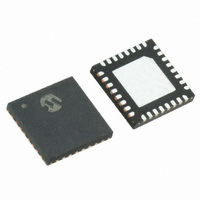
MRF89XA-I/MQ Microchip Technology, MRF89XA-I/MQ Datasheet - Page 68

MRF89XA-I/MQ
Manufacturer Part Number
MRF89XA-I/MQ
Description
TXRX ISM SUB-GHZ ULP 32QFN
Manufacturer
Microchip Technology
Specifications of MRF89XA-I/MQ
Package / Case
32-WFQFN Exposed Pad
Frequency
863MHz ~ 870MHz, 902MHz ~ 928MHz, 950MHz ~ 960MHz
Data Rate - Maximum
200kbps
Modulation Or Protocol
FSK, OOK
Applications
ISM
Power - Output
12.5dBm
Sensitivity
-113dBm
Voltage - Supply
2.1 V ~ 3.6 V
Current - Receiving
3mA
Current - Transmitting
25mA
Data Interface
PCB, Surface Mount
Antenna Connector
PCB, Surface Mount
Operating Temperature
-40°C ~ 85°C
Number Of Receivers
1
Number Of Transmitters
1
Wireless Frequency
863 MHz to 870 MHz, 902 MHz to 928 MHz, 950 MHz to 960 MHz
Interface Type
SPI
Noise Figure
- 112 dBc
Output Power
- 8.5 dBm, + 12.5 dBm
Operating Supply Voltage
2.1 V to 3.6 V
Maximum Operating Temperature
+ 85 C
Mounting Style
SMD/SMT
Maximum Data Rate
256 Kbps
Maximum Supply Current
25 mA
Minimum Operating Temperature
- 40 C
Modulation
FSK
Lead Free Status / RoHS Status
Lead free / RoHS Compliant
Memory Size
-
Lead Free Status / Rohs Status
Lead free / RoHS Compliant
Available stocks
Company
Part Number
Manufacturer
Quantity
Price
Company:
Part Number:
MRF89XA-I/MQ
Manufacturer:
MICROCHIP
Quantity:
12 000
3.4.6
The center frequency, f
chart in Figure 3-8 illustrates the receiver bandwidth
when the BUTFILV<3:0> bits (FILCREG<3:0>) are
changed when the polyphase filter is activated.
Table 4-2 in Section 4.6 “Crystal Specification and
Selection Guidelines” suggests a few filter settings in
OOK mode along with the corresponding passive filter
bandwidth and the accepted tolerance on the crystal
reference.
FIGURE 3-8:
3.4.7.2
In OOK mode, the RSSI evaluates the signal strength
by sampling I(t) and Q(t) signals 16 times in each
period of the chosen IF2 frequency (refer to
Section 2.10.1 “Receiver Architecture”). In FSK
mode, the signals are sampled 16 times in each f
period, f
companion transmitter. An average is then performed
over a sliding window of 16 samples. Therefore, the
RSSI output register RSTSREG (RSSIVAL<7:0>) is
updated 16 times in each f
DS70622B-page 68
MRF89XA
450
400
350
300
250
200
150
100
50
0
dev
0
CHANNEL FILTERS SETTING IN
OOK MODE
being the frequency deviation of the
Acquisition Time
ACTUAL BW OF POLYPHASE FILTER
o
2
, is always set to 100 kHz. The
dev
or IF2 period.
4
Polyphase Filter's BW, OOK
6
Val BUTFILV<3:0> [d]
POLCFV<3:0> = 0011
Preliminary
dev
8
3.4.7
After filtering, the In-phase and Quadrature signals are
amplified by a chain of 11 amplifiers, each with 6dB
gain. The outputs of these amplifiers are used to
evaluate the RSSI.
3.4.7.1
When the RSSI resolution is 0.5 dB, the absolute
accuracy is not expected to be better than ±3dB due to
process and external component variation. Higher
accuracy
measurements will require additional calibration.
The following settings are recommended:
• FSK Mode: Ensure that the f
• OOK reception: Ensure that the f
described in the FDEVREG register (Register 2-3)
through the FDVAL<7:0> bits) remains consistent
with
companion transmitter.
described in the FDEVREG register (Register 2-3)
through the FDVAL<7:0> bits)) is equal with the fre-
quency of the I(t) and Q(t) signals (that is, the sec-
ond Intermediate Frequency, IF2, of the receiver).
Note that this equals f
polyphase filter.
the
10
RECEIVED SIGNAL STRENGTH
(RSSI)
while
Resolution and Accuracy
actual
performing
12
frequency
© 2010 Microchip Technology Inc.
o
, the center frequency of the
Actual
BW
deviation
14
dev
absolute
dev
Theoretical
BW
parameter (as
parameter (as
of
16
RSSI
the


