ATEVK1105 Atmel, ATEVK1105 Datasheet - Page 156
ATEVK1105
Manufacturer Part Number
ATEVK1105
Description
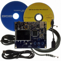
KIT EVAL FOR AT32UC3A0
Manufacturer
Atmel
Series
AVR®32r
Type
MCUr
Datasheets
1.ATAVRONE-PROBECBL.pdf
(16 pages)
2.ATEVK1104.pdf
(826 pages)
3.ATEVK1105.pdf
(28 pages)
Specifications of ATEVK1105
Contents
Evaluation Board, Software and Documentation
Processor To Be Evaluated
AT32UC3A0512
Processor Series
AVR
Data Bus Width
32 bit
Interface Type
USART, TWI, USB, SPI, Ethernet
Operating Supply Voltage
3.3 V
Silicon Manufacturer
Atmel
Core Architecture
AVR
Core Sub-architecture
AVR UC3
Silicon Core Number
AT32UC3A0512
Silicon Family Name
AVR
Kit Contents
Board CD Docs
Rohs Compliant
Yes
For Use With/related Products
AT32UC3A0
Lead Free Status / RoHS Status
Lead free / RoHS Compliant


21.4.9
21.4.10
21.5
21.5.1
Table 21-1.
21.5.2
32058J–AVR32–04/11
Offset
0x0C
0x1C
0x00
0x04
0x08
0x10
0x14
0x18
0x20
User Interface
0x00C0 - 0x00FF
0x0000 - 0x003F
0x0040 - 0x007F
0x0080 - 0x00BF
0x0100 - 0x013F
Address Range
Priority
Error Handling
Memory Map Overview
Channel Memory Map
Register Map Overview
-
-
Memory Address Reload Register
Transfer Counter Reload Register
If more then one PDCA channel is requesting transfer at a given time, the PDCA channels are
prioritized by their channel number. Channels with lower numbers have priority over channels
with higher numbers, giving channel 0 the highest priority.
If the memory address is set to point to an invalid location in memory, an error will occur when
the PDCA tries to perform a transfer. When an error occurs, the Transfer Error flag (TERR) in
the Interrupt Status Register will be set and the DMA channel that caused the error will be
stopped. In order to restart the channel, the user must program the Memory Address Register to
a valid address and then write the Error Clear bit (ECLR) in the Control Register (CR) to ‘1’. An
interrupt can optionally be triggered on errors by writing the TERR-bit in the Interrupt Enable
Register (IER) to ‘1’.
Note:
Memory Address Register
Peripheral Select Register
Transfer Counter Register
Interrupt Enable Register
Control Register
Status Register
Mode Register
The number of channels is implementation specific. See part documentation for details.
Register
DMA channel n-1 configuration registers
DMA channel 0 configuration registers
DMA channel 1 configuration registers
DMA channel 2 configuration registers
DMA channel 3 configuration registers
DMA channel 4 configuration registers
Register Name
MARR
TCRR
MAR
PSR
TCR
MR
IER
CR
SR
Contents
-
Read/Write
Read/Write
Read/Write
Read/Write
Read/Write
Read/Write
Read-only
Write-only
Write-only
Access
AT32UC3A
0x00000000
0x00000000
0x00000000
0x00000000
0x00000000
0x00000000
Reset
*
-
-
156
Related parts for ATEVK1105
Image
Part Number
Description
Manufacturer
Datasheet
Request
R

Part Number:
Description:
DEV KIT FOR AVR/AVR32
Manufacturer:
Atmel
Datasheet:

Part Number:
Description:
INTERVAL AND WIPE/WASH WIPER CONTROL IC WITH DELAY
Manufacturer:
ATMEL Corporation
Datasheet:
Part Number:
Description:
Low-Voltage Voice-Switched IC for Hands-Free Operation
Manufacturer:
ATMEL Corporation
Datasheet:
Part Number:
Description:
MONOLITHIC INTEGRATED FEATUREPHONE CIRCUIT
Manufacturer:
ATMEL Corporation
Datasheet:
Part Number:
Description:
AM-FM Receiver IC U4255BM-M
Manufacturer:
ATMEL Corporation
Datasheet:
Part Number:
Description:
Monolithic Integrated Feature Phone Circuit
Manufacturer:
ATMEL Corporation
Datasheet:
Part Number:
Description:
Multistandard Video-IF and Quasi Parallel Sound Processing
Manufacturer:
ATMEL Corporation
Datasheet:
Part Number:
Description:
High-performance EE PLD
Manufacturer:
ATMEL Corporation
Datasheet:
Part Number:
Description:
8-bit Flash Microcontroller
Manufacturer:
ATMEL Corporation
Datasheet:
Part Number:
Description:
2-Wire Serial EEPROM
Manufacturer:
ATMEL Corporation
Datasheet: