ATEVK1105 Atmel, ATEVK1105 Datasheet - Page 744
ATEVK1105
Manufacturer Part Number
ATEVK1105
Description
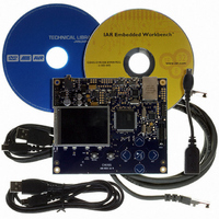
KIT EVAL FOR AT32UC3A0
Manufacturer
Atmel
Series
AVR®32r
Type
MCUr
Datasheets
1.ATAVRONE-PROBECBL.pdf
(16 pages)
2.ATEVK1104.pdf
(826 pages)
3.ATEVK1105.pdf
(28 pages)
Specifications of ATEVK1105
Contents
Evaluation Board, Software and Documentation
Processor To Be Evaluated
AT32UC3A0512
Processor Series
AVR
Data Bus Width
32 bit
Interface Type
USART, TWI, USB, SPI, Ethernet
Operating Supply Voltage
3.3 V
Silicon Manufacturer
Atmel
Core Architecture
AVR
Core Sub-architecture
AVR UC3
Silicon Core Number
AT32UC3A0512
Silicon Family Name
AVR
Kit Contents
Board CD Docs
Rohs Compliant
Yes
For Use With/related Products
AT32UC3A0
Lead Free Status / RoHS Status
Lead free / RoHS Compliant


Figure 36-2. TAP Controller State Diagram
36.6.2
36.6.2.1
32058J–AVR32–04/11
Typical sequence
Scanning in JTAG instruction
1
0
Assuming Run-Test/Idle is the present state, a typical scenario for using the JTAG interface is:
At the TMS input, apply the sequence 1, 1, 0, 0 at the rising edges of TCK to enter the Shift
Instruction Register - Shift-IR state. While in this state, shift the 5 bits of the JTAG instructions
into the JTAG instruction register from the TDI input at the rising edge of TCK. The TMS input
must be held low during input of the 4 LSBs in order to remain in the Shift-IR state. The JTAG
Instruction selects a particular Data Register as path between TDI and TDO and controls the cir-
cuitry surrounding the selected Data Register.
Apply the TMS sequence 1, 1, 0 to re-enter the Run-Test/Idle state. The instruction is latched
onto the parallel output from the shift register path in the Update-IR state. The Exit-IR, Pause-IR,
and Exit2-IR states are only used for navigating the state machine.
Test-Logic-
Run-Test/
Reset
Idle
0
1
0
1
1
Capture-DR
Update-DR
Pause-DR
Select-DR
Exit1-DR
Exit2-DR
Shift-DR
Scan
0
0
1
0
1
1
0
0
0
1
1
0
1
1
Capture-IR
Update-IR
Pause-IR
Select-IR
Exit1-IR
Exit2-IR
Shift-IR
Scan
0
0
1
0
1
1
0
0
0
1
1
AT32UC3A
744
Related parts for ATEVK1105
Image
Part Number
Description
Manufacturer
Datasheet
Request
R

Part Number:
Description:
DEV KIT FOR AVR/AVR32
Manufacturer:
Atmel
Datasheet:

Part Number:
Description:
INTERVAL AND WIPE/WASH WIPER CONTROL IC WITH DELAY
Manufacturer:
ATMEL Corporation
Datasheet:
Part Number:
Description:
Low-Voltage Voice-Switched IC for Hands-Free Operation
Manufacturer:
ATMEL Corporation
Datasheet:
Part Number:
Description:
MONOLITHIC INTEGRATED FEATUREPHONE CIRCUIT
Manufacturer:
ATMEL Corporation
Datasheet:
Part Number:
Description:
AM-FM Receiver IC U4255BM-M
Manufacturer:
ATMEL Corporation
Datasheet:
Part Number:
Description:
Monolithic Integrated Feature Phone Circuit
Manufacturer:
ATMEL Corporation
Datasheet:
Part Number:
Description:
Multistandard Video-IF and Quasi Parallel Sound Processing
Manufacturer:
ATMEL Corporation
Datasheet:
Part Number:
Description:
High-performance EE PLD
Manufacturer:
ATMEL Corporation
Datasheet:
Part Number:
Description:
8-bit Flash Microcontroller
Manufacturer:
ATMEL Corporation
Datasheet:
Part Number:
Description:
2-Wire Serial EEPROM
Manufacturer:
ATMEL Corporation
Datasheet: