ATEVK1105 Atmel, ATEVK1105 Datasheet - Page 95
ATEVK1105
Manufacturer Part Number
ATEVK1105
Description
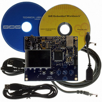
KIT EVAL FOR AT32UC3A0
Manufacturer
Atmel
Series
AVR®32r
Type
MCUr
Datasheets
1.ATAVRONE-PROBECBL.pdf
(16 pages)
2.ATEVK1104.pdf
(826 pages)
3.ATEVK1105.pdf
(28 pages)
Specifications of ATEVK1105
Contents
Evaluation Board, Software and Documentation
Processor To Be Evaluated
AT32UC3A0512
Processor Series
AVR
Data Bus Width
32 bit
Interface Type
USART, TWI, USB, SPI, Ethernet
Operating Supply Voltage
3.3 V
Silicon Manufacturer
Atmel
Core Architecture
AVR
Core Sub-architecture
AVR UC3
Silicon Core Number
AT32UC3A0512
Silicon Family Name
AVR
Kit Contents
Board CD Docs
Rohs Compliant
Yes
For Use With/related Products
AT32UC3A0
Lead Free Status / RoHS Status
Lead free / RoHS Compliant


15.5
32058J–AVR32–04/11
Functional Description
The WDT is enabled by writing the EN bit in the CTRL register to one. This also enables the RC
clock for the prescaler. The PSEL bitfield in the same register selects the watchdog timeout
period:
The next timeout period will begin as soon as the watchdog reset has occured and count down
during the reset sequence. Care must be taken when selecting the PSEL value so that the time-
out period is greater than the startup time of the chip, otherwise a watchdog reset can reset the
chip before any code has been run.
To avoid accidental disabling of the watchdog, the CTRL register must be written twice, first with
the KEY field set to 0x55, then 0xAA without changing the other bitfields. Failure to do so will
cause the write operation to be ignored, and CTRL does not change value.
The CLR register must be written with any value with regular intervals shorter than the watchdog
timeout period. Otherwise, the device will receive a soft reset, and the code will start executing
from the boot vector.
When the WDT is enabled, it is not possible to enter Static mode. Attempting to do so will result
in entering Shutdown mode, leaving the WDT operational.
T
WDT
= 2
(PSEL+1)
/ f
RC
AT32UC3A
95
Related parts for ATEVK1105
Image
Part Number
Description
Manufacturer
Datasheet
Request
R

Part Number:
Description:
DEV KIT FOR AVR/AVR32
Manufacturer:
Atmel
Datasheet:

Part Number:
Description:
INTERVAL AND WIPE/WASH WIPER CONTROL IC WITH DELAY
Manufacturer:
ATMEL Corporation
Datasheet:
Part Number:
Description:
Low-Voltage Voice-Switched IC for Hands-Free Operation
Manufacturer:
ATMEL Corporation
Datasheet:
Part Number:
Description:
MONOLITHIC INTEGRATED FEATUREPHONE CIRCUIT
Manufacturer:
ATMEL Corporation
Datasheet:
Part Number:
Description:
AM-FM Receiver IC U4255BM-M
Manufacturer:
ATMEL Corporation
Datasheet:
Part Number:
Description:
Monolithic Integrated Feature Phone Circuit
Manufacturer:
ATMEL Corporation
Datasheet:
Part Number:
Description:
Multistandard Video-IF and Quasi Parallel Sound Processing
Manufacturer:
ATMEL Corporation
Datasheet:
Part Number:
Description:
High-performance EE PLD
Manufacturer:
ATMEL Corporation
Datasheet:
Part Number:
Description:
8-bit Flash Microcontroller
Manufacturer:
ATMEL Corporation
Datasheet:
Part Number:
Description:
2-Wire Serial EEPROM
Manufacturer:
ATMEL Corporation
Datasheet: