ATEVK1105 Atmel, ATEVK1105 Datasheet - Page 228
ATEVK1105
Manufacturer Part Number
ATEVK1105
Description
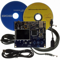
KIT EVAL FOR AT32UC3A0
Manufacturer
Atmel
Series
AVR®32r
Type
MCUr
Datasheets
1.ATAVRONE-PROBECBL.pdf
(16 pages)
2.ATEVK1104.pdf
(826 pages)
3.ATEVK1105.pdf
(28 pages)
Specifications of ATEVK1105
Contents
Evaluation Board, Software and Documentation
Processor To Be Evaluated
AT32UC3A0512
Processor Series
AVR
Data Bus Width
32 bit
Interface Type
USART, TWI, USB, SPI, Ethernet
Operating Supply Voltage
3.3 V
Silicon Manufacturer
Atmel
Core Architecture
AVR
Core Sub-architecture
AVR UC3
Silicon Core Number
AT32UC3A0512
Silicon Family Name
AVR
Kit Contents
Board CD Docs
Rohs Compliant
Yes
For Use With/related Products
AT32UC3A0
Lead Free Status / RoHS Status
Lead free / RoHS Compliant


24.10.6.2
24.11
24.11.1
24.11.2
32058J-AVR32-04/11
Internal Address Usage
Data Transmit with the PDC
Data Receive with the PDC
10-bit Slave Addressing
For a slave address higher than 7 bits, the user must configure the address size (IADRSZ) and
set the other slave address bits in the internal address register (IADR). The two remaining Inter-
nal address bytes, IADR[15:8] and IADR[23:16] can be used the same as in 7-bit Slave
Addressing.
Example: Address a 10-bit device:
(10-bit device address is b1 b2 b3 b4 b5 b6 b7 b8 b9 b10)
1. Program IADRSZ = 1,
2. Program DADR with 1 1 1 1 0 b1 b2 (b1 is the MSB of the 10-bit address, b2, etc.)
3. Program IADR with b3 b4 b5 b6 b7 b8 b9 b10 (b10 is the LSB of the 10-bit address)
Figure 24.11
the use of internal addresses to access the device.
The use of the PDC significantly reduces the CPU load.
To assure correct implementation, respect the following programming sequences:
1. Initialize the transmit PDC (memory pointers, size, etc.).
2. Configure the master mode (DADR, CKDIV, etc.).
3. Start the transfer by setting the PDC TXTEN bit.
4. Wait for the PDC end TX flag.
5. Disable the PDC by setting the PDC TXDIS bit.
1. Initialize the receive PDC (memory pointers, size - 1, etc.).
2. Configure the master mode (DADR, CKDIV, etc.).
3. Start the transfer by setting the PDC RXTEN bit.
4. Wait for the PDC end RX flag.
5. Disable the PDC by setting the PDC RXDIS bit.
S
T
A
R
T
M
S
B
Using the Peripheral DMA Controller (PDC)
Address
Device
0
below shows a byte write to an Atmel AT24LC512 EEPROM. This demonstrates
S
B
L
W
W
R
E
T
R
I
/
A
C
K
WORD ADDRESS
M
S
B
FIRST
A
C
K
WORD ADDRESS
SECOND
L
S
B
A
C
K
DATA
A
C
K
S
O
P
T
AT32UC3A
228
Related parts for ATEVK1105
Image
Part Number
Description
Manufacturer
Datasheet
Request
R

Part Number:
Description:
DEV KIT FOR AVR/AVR32
Manufacturer:
Atmel
Datasheet:

Part Number:
Description:
INTERVAL AND WIPE/WASH WIPER CONTROL IC WITH DELAY
Manufacturer:
ATMEL Corporation
Datasheet:
Part Number:
Description:
Low-Voltage Voice-Switched IC for Hands-Free Operation
Manufacturer:
ATMEL Corporation
Datasheet:
Part Number:
Description:
MONOLITHIC INTEGRATED FEATUREPHONE CIRCUIT
Manufacturer:
ATMEL Corporation
Datasheet:
Part Number:
Description:
AM-FM Receiver IC U4255BM-M
Manufacturer:
ATMEL Corporation
Datasheet:
Part Number:
Description:
Monolithic Integrated Feature Phone Circuit
Manufacturer:
ATMEL Corporation
Datasheet:
Part Number:
Description:
Multistandard Video-IF and Quasi Parallel Sound Processing
Manufacturer:
ATMEL Corporation
Datasheet:
Part Number:
Description:
High-performance EE PLD
Manufacturer:
ATMEL Corporation
Datasheet:
Part Number:
Description:
8-bit Flash Microcontroller
Manufacturer:
ATMEL Corporation
Datasheet:
Part Number:
Description:
2-Wire Serial EEPROM
Manufacturer:
ATMEL Corporation
Datasheet: