ATEVK1105 Atmel, ATEVK1105 Datasheet - Page 63
ATEVK1105
Manufacturer Part Number
ATEVK1105
Description
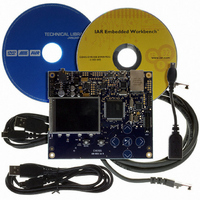
KIT EVAL FOR AT32UC3A0
Manufacturer
Atmel
Series
AVR®32r
Type
MCUr
Datasheets
1.ATAVRONE-PROBECBL.pdf
(16 pages)
2.ATEVK1104.pdf
(826 pages)
3.ATEVK1105.pdf
(28 pages)
Specifications of ATEVK1105
Contents
Evaluation Board, Software and Documentation
Processor To Be Evaluated
AT32UC3A0512
Processor Series
AVR
Data Bus Width
32 bit
Interface Type
USART, TWI, USB, SPI, Ethernet
Operating Supply Voltage
3.3 V
Silicon Manufacturer
Atmel
Core Architecture
AVR
Core Sub-architecture
AVR UC3
Silicon Core Number
AT32UC3A0512
Silicon Family Name
AVR
Kit Contents
Board CD Docs
Rohs Compliant
Yes
For Use With/related Products
AT32UC3A0
Lead Free Status / RoHS Status
Lead free / RoHS Compliant


13.5.8.4
13.5.9
13.5.10
13.5.11
32058J–AVR32–04/11
Divided PB clocks
Debug operation
Reset Controller
Generic clock implementation
In AT32UC3A, there are 6 generic clocks. These are allocated to different functions as shown in
Table
Table 13-2.
The clock generator in the Power Manager provides divided PBA and PBB clocks for use by
peripherals that require a prescaled PBx clock. This is described in the documentation for the
relevant modules.
The divided clocks are not directly maskable, but are stopped in sleep modes where the PBx
clocks are stopped.
During a debug session, the user may need to halt the system to inspect memory and CPU reg-
isters. The clocks normally keep running during this debug operation, but some peripherals may
require the clocks to be stopped, e.g. to prevent timer overflow, which would cause the program
to fail. For this reason, peripherals on the PBA and PBB buses may use “debug qualified” PBx
clocks. This is described in the documentation for the relevant modules. The divided PBx clocks
are always debug qualified clocks.
Debug qualified PB clocks are stopped during debug operation. The debug system can option-
ally keep these clocks running during the debug operation. This is described in the
documentation for the On-Chip Debug system.
The Reset Controller collects the various reset sources in the system and generates hard and
soft resets for the digital logic.
The device contains a Power-On Detector, which keeps the system reset until power is stable.
This eliminates the need for external reset circuitry to guarantee stable operation when powering
up the device.
Clock number
13-2.
0
1
2
3
4
5
Generic clock allocation
Function
GCLK0 pin
GCLK1 pin
GCLK2 pin
GCLK3 pin
USBB
ABDAC
AT32UC3A
63
Related parts for ATEVK1105
Image
Part Number
Description
Manufacturer
Datasheet
Request
R

Part Number:
Description:
DEV KIT FOR AVR/AVR32
Manufacturer:
Atmel
Datasheet:

Part Number:
Description:
INTERVAL AND WIPE/WASH WIPER CONTROL IC WITH DELAY
Manufacturer:
ATMEL Corporation
Datasheet:
Part Number:
Description:
Low-Voltage Voice-Switched IC for Hands-Free Operation
Manufacturer:
ATMEL Corporation
Datasheet:
Part Number:
Description:
MONOLITHIC INTEGRATED FEATUREPHONE CIRCUIT
Manufacturer:
ATMEL Corporation
Datasheet:
Part Number:
Description:
AM-FM Receiver IC U4255BM-M
Manufacturer:
ATMEL Corporation
Datasheet:
Part Number:
Description:
Monolithic Integrated Feature Phone Circuit
Manufacturer:
ATMEL Corporation
Datasheet:
Part Number:
Description:
Multistandard Video-IF and Quasi Parallel Sound Processing
Manufacturer:
ATMEL Corporation
Datasheet:
Part Number:
Description:
High-performance EE PLD
Manufacturer:
ATMEL Corporation
Datasheet:
Part Number:
Description:
8-bit Flash Microcontroller
Manufacturer:
ATMEL Corporation
Datasheet:
Part Number:
Description:
2-Wire Serial EEPROM
Manufacturer:
ATMEL Corporation
Datasheet: