ATEVK1105 Atmel, ATEVK1105 Datasheet - Page 226
ATEVK1105
Manufacturer Part Number
ATEVK1105
Description
KIT EVAL FOR AT32UC3A0
Manufacturer
Atmel
Series
AVR®32r
Type
MCUr
Datasheets
1.ATAVRONE-PROBECBL.pdf
(16 pages)
2.ATEVK1104.pdf
(826 pages)
3.ATEVK1105.pdf
(28 pages)
Specifications of ATEVK1105
Contents
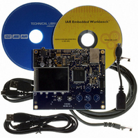
Evaluation Board, Software and Documentation
Processor To Be Evaluated
AT32UC3A0512
Processor Series
AVR
Data Bus Width
32 bit
Interface Type
USART, TWI, USB, SPI, Ethernet
Operating Supply Voltage
3.3 V
Silicon Manufacturer
Atmel
Core Architecture
AVR
Core Sub-architecture
AVR UC3
Silicon Core Number
AT32UC3A0512
Silicon Family Name
AVR
Kit Contents
Board CD Docs
Rohs Compliant
Yes
For Use With/related Products
AT32UC3A0
Lead Free Status / RoHS Status
Lead free / RoHS Compliant


Figure 24-9. Master Read with One Data Byte
Figure 24-10. Master Read with Multiple Data Bytes
24.10.6
24.10.6.1
32058J-AVR32-04/11
TXCOMP
RXRDY
TWD
Internal Address
S
7-bit Slave Addressing
Write START Bit
DADR
RXRDY bit is set in the status register, a character has been received in the receive-holding reg-
ister (RHR). The RXRDY bit is reset when reading the RHR.
When a single data byte read is performed, with or without internal address (IADR), the START
and STOP bits must be set at the same time. See
performed, with or without IADR, the STOP bit must be set after the next-to-last data received.
See
RXRDY is used as Receive Ready for the PDC receive channel.
The TWI interface can perform various transfer formats: Transfers with 7-bit slave address
devices and 10-bit slave address devices.
When Addressing 7-bit slave devices, the internal address bytes are used to perform random
address (read or write) accesses to reach one or more data bytes, within a memory page loca-
tion in a serial memory, for example. When performing read operations with an internal address,
the TWI performs a write operation to set the internal address into the slave device, and then
switch to Master Receiver mode. Note that the second start condition (after sending the IADR) is
sometimes called “repeated start” (Sr) in I2C fully-compatible devices. See
Figure 24-11
The three internal address bytes are configurable through the Master Mode register (MMR).
TXCOMP
RXRDY
R
Figure
TWD
A
24-10. For Internal Address usage see
and
S
DATA n
Write START &
Figure 24.11
STOP Bit
DADR
Read RHR
A
DATA n
for Master Write operation with internal address.
DATA (n+1)
R
A
A
DATA (n+1)
Read RHR
DATA
DATA (n+m)-1
Figure
”Internal Address” on page
Read RHR
N
24-9. When a multiple data byte read is
DATA (n+m)-1
P
A
Read RHR
after next-to-last data read
DATA (n+m)
Write STOP Bit
AT32UC3A
Figure
226.
N
24-12. See
DATA (n+m)
Read RHR
P
226
Related parts for ATEVK1105
Image
Part Number
Description
Manufacturer
Datasheet
Request
R

Part Number:
Description:
DEV KIT FOR AVR/AVR32
Manufacturer:
Atmel
Datasheet:

Part Number:
Description:
INTERVAL AND WIPE/WASH WIPER CONTROL IC WITH DELAY
Manufacturer:
ATMEL Corporation
Datasheet:
Part Number:
Description:
Low-Voltage Voice-Switched IC for Hands-Free Operation
Manufacturer:
ATMEL Corporation
Datasheet:
Part Number:
Description:
MONOLITHIC INTEGRATED FEATUREPHONE CIRCUIT
Manufacturer:
ATMEL Corporation
Datasheet:
Part Number:
Description:
AM-FM Receiver IC U4255BM-M
Manufacturer:
ATMEL Corporation
Datasheet:
Part Number:
Description:
Monolithic Integrated Feature Phone Circuit
Manufacturer:
ATMEL Corporation
Datasheet:
Part Number:
Description:
Multistandard Video-IF and Quasi Parallel Sound Processing
Manufacturer:
ATMEL Corporation
Datasheet:
Part Number:
Description:
High-performance EE PLD
Manufacturer:
ATMEL Corporation
Datasheet:
Part Number:
Description:
8-bit Flash Microcontroller
Manufacturer:
ATMEL Corporation
Datasheet:
Part Number:
Description:
2-Wire Serial EEPROM
Manufacturer:
ATMEL Corporation
Datasheet: