C8051F120DK Silicon Laboratories Inc, C8051F120DK Datasheet - Page 199
C8051F120DK
Manufacturer Part Number
C8051F120DK
Description
DEVKIT-F120/21/22/23/24/25/26/27
Manufacturer
Silicon Laboratories Inc
Type
MCUr
Datasheet
1.C8051F120DK.pdf
(350 pages)
Specifications of C8051F120DK
Contents
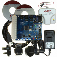
Evaluation Board, Power Supply, USB Cables, Adapter and Documentation
Processor To Be Evaluated
C8051F12x and C8051F13x
Interface Type
USB
Silicon Manufacturer
Silicon Labs
Core Architecture
8051
Silicon Core Number
C8051F120
Silicon Family Name
C8051F12x
Lead Free Status / RoHS Status
Contains lead / RoHS non-compliant
For Use With/related Products
C8051F120, 121, 122, 123, 124, 125, 126, 127
Lead Free Status / Rohs Status
Lead free / RoHS Compliant
Other names
336-1224
Available stocks
Company
Part Number
Manufacturer
Quantity
Price
Company:

Part Number:
C8051F120DK
Manufacturer:
SiliconL
Quantity:
4


C8051F120/1/2/3/4/5/6/7
C8051F130/1/2/3
15. Flash Memory
All devices include either 128 kB (C8051F12x and C8051F130/1) or 64 kB (C8051F132/3) of on-chip,
reprogrammable Flash memory for program code or non-volatile data storage. An additional 256-byte
page of Flash is also included for non-volatile data storage. The Flash memory can be programmed in-sys-
tem through the JTAG interface, or by software using the MOVX write instructions. Once cleared to logic 0,
a Flash bit must be erased to set it back to logic 1. Bytes should be erased (set to 0xFF) before being
reprogrammed. Flash write and erase operations are automatically timed by hardware for proper execu-
tion. During a Flash erase or write, the FLBUSY bit in the FLSTAT register is set to ‘1’ (see SFR Definition
16.5). During this time, instructions that are located in the prefetch buffer or the branch target cache can be
executed, but the processor will stall until the erase or write is completed if instruction data must be fetched
from Flash memory. Interrupts that have been pre-loaded into the branch target cache can also be ser-
viced at this time, if the current code is also executing from the prefetch engine or cache memory. Any
interrupts that are not pre-loaded into cache, or that occur while the core is halted, will be held in a pending
state during the Flash write/erase operation, and serviced in priority order once the Flash operation has
completed. Refer to Table 15.1 for the electrical characteristics of the Flash memory.
15.1. Programming the Flash Memory
The simplest means of programming the Flash memory is through the JTAG interface using programming
tools provided by Silicon Labs or a third party vendor. This is the only means for programming a non-initial-
ized device. For details on the JTAG commands to program Flash memory, see
Section “25. JTAG (IEEE
1149.1)” on page 341
.
The Flash memory can be programmed from software using the MOVX write instruction with the address
and data byte to be programmed provided as normal operands. Before writing to Flash memory using
MOVX, Flash write operations must be enabled by setting the PSWE Program Store Write Enable bit
(PSCTL.0) to logic 1. This directs the MOVX writes to Flash memory instead of to XRAM, which is the
default target. The PSWE bit remains set until cleared by software. To avoid errant Flash writes, it is rec-
ommended that interrupts be disabled while the PSWE bit is logic 1.
Flash memory is read using the MOVC instruction. MOVX reads are always directed to XRAM, regardless
of the state of PSWE.
On the devices with 128 kB of Flash, the COBANK bits in the PSBANK register (SFR Definition 11.1)
determine which of the upper three Flash banks are mapped to the address range 0x08000 to 0x0FFFF for
Flash writes, reads and erases.
For devices with 64 kB of Flash. the COBANK bits should always remain set to ‘01’ to ensure that Flash
write, erase, and read operations are valid.
NOTE: To ensure the integrity of Flash memory contents, it is strongly recommended that the on-
chip V
monitor be enabled by connecting the V
monitor enable pin (MONEN) to V
and set-
DD
DD
DD
ting the PORSF bit in the RSTSRC register to ‘1’ in any system that writes and/or erases Flash
memory from software. See “Reset Sources” on page 177 for more information.
A write to Flash memory can clear bits but cannot set them; only an erase operation can set bits in Flash.
A byte location to be programmed must be erased before a new value can be written .
Write/Erase timing is automatically controlled by hardware. Note that on the 128 k Flash versions, 1024
bytes beginning at location 0x1FC00 are reserved. Flash writes and erases targeting the reserved area
should be avoided.
Rev. 1.4
199
Related parts for C8051F120DK
Image
Part Number
Description
Manufacturer
Datasheet
Request
R

Part Number:
Description:
SMD/C°/SINGLE-ENDED OUTPUT SILICON OSCILLATOR
Manufacturer:
Silicon Laboratories Inc
Part Number:
Description:
Manufacturer:
Silicon Laboratories Inc
Datasheet:
Part Number:
Description:
N/A N/A/SI4010 AES KEYFOB DEMO WITH LCD RX
Manufacturer:
Silicon Laboratories Inc
Datasheet:
Part Number:
Description:
N/A N/A/SI4010 SIMPLIFIED KEY FOB DEMO WITH LED RX
Manufacturer:
Silicon Laboratories Inc
Datasheet:
Part Number:
Description:
N/A/-40 TO 85 OC/EZLINK MODULE; F930/4432 HIGH BAND (REV E/B1)
Manufacturer:
Silicon Laboratories Inc
Part Number:
Description:
EZLink Module; F930/4432 Low Band (rev e/B1)
Manufacturer:
Silicon Laboratories Inc
Part Number:
Description:
I°/4460 10 DBM RADIO TEST CARD 434 MHZ
Manufacturer:
Silicon Laboratories Inc
Part Number:
Description:
I°/4461 14 DBM RADIO TEST CARD 868 MHZ
Manufacturer:
Silicon Laboratories Inc
Part Number:
Description:
I°/4463 20 DBM RFSWITCH RADIO TEST CARD 460 MHZ
Manufacturer:
Silicon Laboratories Inc
Part Number:
Description:
I°/4463 20 DBM RADIO TEST CARD 868 MHZ
Manufacturer:
Silicon Laboratories Inc
Part Number:
Description:
I°/4463 27 DBM RADIO TEST CARD 868 MHZ
Manufacturer:
Silicon Laboratories Inc
Part Number:
Description:
I°/4463 SKYWORKS 30 DBM RADIO TEST CARD 915 MHZ
Manufacturer:
Silicon Laboratories Inc
Part Number:
Description:
N/A N/A/-40 TO 85 OC/4463 RFMD 30 DBM RADIO TEST CARD 915 MHZ
Manufacturer:
Silicon Laboratories Inc
Part Number:
Description:
I°/4463 20 DBM RADIO TEST CARD 169 MHZ
Manufacturer:
Silicon Laboratories Inc