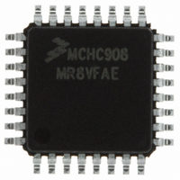
MCHC908MR8VFAE Freescale Semiconductor, MCHC908MR8VFAE Datasheet - Page 325

MCHC908MR8VFAE
Manufacturer Part Number
MCHC908MR8VFAE
Description
IC MCU 8K FLASH 8MHZ PWM 32-LQFP
Manufacturer
Freescale Semiconductor
Series
HC08r
Datasheet
1.MCHC908MR8VFAE.pdf
(372 pages)
Specifications of MCHC908MR8VFAE
Core Processor
HC08
Core Size
8-Bit
Speed
8MHz
Connectivity
SCI
Peripherals
LVD, POR, PWM
Number Of I /o
16
Program Memory Size
8KB (8K x 8)
Program Memory Type
FLASH
Ram Size
256 x 8
Voltage - Supply (vcc/vdd)
4.5 V ~ 5.5 V
Data Converters
A/D 7x10b
Oscillator Type
Internal
Operating Temperature
-40°C ~ 105°C
Package / Case
32-LQFP
Processor Series
HC08MR
Core
HC08
Data Bus Width
8 bit
Data Ram Size
512 B
Interface Type
SCI, SPI
Maximum Clock Frequency
8 MHz
Number Of Programmable I/os
33
Number Of Timers
4
Maximum Operating Temperature
+ 105 C
Mounting Style
SMD/SMT
Development Tools By Supplier
FSICEBASE, M68CBL05CE
Minimum Operating Temperature
- 40 C
On-chip Adc
8 bit, 8 Channel
Lead Free Status / RoHS Status
Lead free / RoHS Compliant
Eeprom Size
-
Lead Free Status / Rohs Status
Details
Available stocks
Company
Part Number
Manufacturer
Quantity
Price
Company:
Part Number:
MCHC908MR8VFAE
Manufacturer:
Freescale
Quantity:
8 393
Company:
Part Number:
MCHC908MR8VFAE
Manufacturer:
Freescale Semiconductor
Quantity:
10 000
- Current page: 325 of 372
- Download datasheet (4Mb)
MC68HC908MR8 — Rev 4.1
Freescale Semiconductor
ADICLK — ADC Input Clock Select Bit
MODE1:MODE0 — Modes of Result Justification Bits
ADICLK selects either bus clock or CGMXCLK as the input clock
source to generate the internal ADC clock. Reset selects CGMXCLK
as the ADC clock source.
If the external clock (CGMXCLK) is equal or greater than 1 MHz,
CGMXCLK can be used as the clock source for the ADC. If
CGMXCLK is less than 1 MHz, use the PLL-generated bus clock as
the clock source. As long as the internal ADC clock is at f
operation can be guaranteed.
MODE1:MODE0 selects among four modes of operation. The
manner in which the ADC conversion results will be placed in the ADC
data registers is controlled by these modes of operation. Reset
returns right-justified mode.
1 = Internal bus clock
0 = External clock, CGMXCLK
00 = 8-bit truncation mode
01 = Right justified mode
10 = Left justified mode
11 = Left justified sign data mode
Analog-to-Digital Converter (ADC)
ADIV2
X = don’t care
0
0
0
0
1
Table 18-2. ADC Clock Divide Ratio
f
ADIC
ADIV1
=
X
0
0
1
1
CGMXCLK or bus frequency
ADIV0
X
0
1
0
1
ADIV[2:0]
ADC input clock /1
ADC input clock /2
ADC input clock /4
ADC input clock /8
ADC input clock /16
ADC Clock Rate
Analog-to-Digital Converter (ADC)
ADIC
Technical Data
I/O Registers
, correct
325
Related parts for MCHC908MR8VFAE
Image
Part Number
Description
Manufacturer
Datasheet
Request
R
Part Number:
Description:
Manufacturer:
Freescale Semiconductor, Inc
Datasheet:
Part Number:
Description:
Manufacturer:
Freescale Semiconductor, Inc
Datasheet:
Part Number:
Description:
Manufacturer:
Freescale Semiconductor, Inc
Datasheet:
Part Number:
Description:
Manufacturer:
Freescale Semiconductor, Inc
Datasheet:
Part Number:
Description:
Manufacturer:
Freescale Semiconductor, Inc
Datasheet:
Part Number:
Description:
Manufacturer:
Freescale Semiconductor, Inc
Datasheet:
Part Number:
Description:
Manufacturer:
Freescale Semiconductor, Inc
Datasheet:
Part Number:
Description:
Manufacturer:
Freescale Semiconductor, Inc
Datasheet:
Part Number:
Description:
Manufacturer:
Freescale Semiconductor, Inc
Datasheet:
Part Number:
Description:
Manufacturer:
Freescale Semiconductor, Inc
Datasheet:
Part Number:
Description:
Manufacturer:
Freescale Semiconductor, Inc
Datasheet:
Part Number:
Description:
Manufacturer:
Freescale Semiconductor, Inc
Datasheet:
Part Number:
Description:
Manufacturer:
Freescale Semiconductor, Inc
Datasheet:
Part Number:
Description:
Manufacturer:
Freescale Semiconductor, Inc
Datasheet:
Part Number:
Description:
Manufacturer:
Freescale Semiconductor, Inc
Datasheet:


