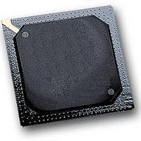
MPC564CZP40 Freescale Semiconductor, MPC564CZP40 Datasheet - Page 1054

MPC564CZP40
Manufacturer Part Number
MPC564CZP40
Description
IC MPU 32BIT W/CODE COMP 388PBGA
Manufacturer
Freescale Semiconductor
Series
MPC5xxr
Specifications of MPC564CZP40
Core Processor
PowerPC
Core Size
32-Bit
Speed
40MHz
Connectivity
CAN, EBI/EMI, SCI, SPI, UART/USART
Peripherals
POR, PWM, WDT
Number Of I /o
56
Program Memory Size
512KB (512K x 8)
Program Memory Type
FLASH
Ram Size
32K x 8
Voltage - Supply (vcc/vdd)
2.5 V ~ 2.7 V
Data Converters
A/D 32x10b
Oscillator Type
External
Operating Temperature
-40°C ~ 85°C
Package / Case
388-BGA
Processor Series
MPC5xx
Core
PowerPC
Data Bus Width
32 bit
Data Ram Size
32 KB
Interface Type
CAN, JTAG, QSPI, SCI, SPI, UART
Maximum Clock Frequency
40 MHz
Number Of Programmable I/os
56
Number Of Timers
2
Operating Supply Voltage
0 V to 5 V
Maximum Operating Temperature
+ 85 C
Mounting Style
SMD/SMT
Minimum Operating Temperature
- 40 C
On-chip Adc
2 (10 bit, 32 Channel)
For Use With
MPC564EVB - KIT EVAL FOR MPC561/562/563/564
Lead Free Status / RoHS Status
Contains lead / RoHS non-compliant
Eeprom Size
-
Lead Free Status / Rohs Status
No
Available stocks
Company
Part Number
Manufacturer
Quantity
Price
Company:
Part Number:
MPC564CZP40
Manufacturer:
Freescale Semiconductor
Quantity:
10 000
- Current page: 1054 of 1420
- Download datasheet (11Mb)
READI Module
24.15 Power Management
This section details the power management features of the READI module.
The READI module is a development interface, and is not expected to function under normal
(non-development) conditions. Therefore power management is required to reduce and minimize power
consumption during normal operation of the part.
24.15.1 Functional Description
The following are the candidates for power management:
24.15.2 Low Power Modes
When the MCU is in sleep, deep-sleep, or low power-down mode, all internal clocks on the MCU are shut
down, including the MCKO. The MSEO signal will be held negated.
Low power mode entry for the MCU will be held off until the READI module has transmitted all existing
messages (in the queues and transmit buffers). During this time, input messages from the development tool
are ignored.
Upon restoration of clocks in normal mode, program and data traces will be synchronized, if enabled.
24-86
TCODE = 57 (0x39)
Header = (Start=0, Mode=0, Control=0)
Data = FF00AAF5 (CPU Data Out)
MCKO
MSEO
MDO[7:0]
Low Power-Down Mode
Sleep, Deep-Sleep and
READI Reset (RSTI)
Disabled Mode
Feature
Table 24-35. Power Management Mechanism Overview
Figure 24-89. DSDO Data Message (CPU Data Out)
00111001
MPC561/MPC563 Reference Manual, Rev. 1.2
11111110
If EVTI is negated at negation of RSTI, the READI module will be
disabled. No trace output will be provided, and output auxiliary port
will be three-stated.
All outputs will be held static.
Output auxiliary signals will be three-stated.
00000001 10101010 01011110 00000001 00000000
Power Saving Mechanism
Don’t care data
(idle clock)
Freescale Semiconductor
Related parts for MPC564CZP40
Image
Part Number
Description
Manufacturer
Datasheet
Request
R

Part Number:
Description:
MPC5 1K0 5%
Manufacturer:
TE Connectivity
Datasheet:

Part Number:
Description:
MPC5 500R 5%
Manufacturer:
TE Connectivity
Datasheet:

Part Number:
Description:
MPC5 5K0 5%
Manufacturer:
Tyco Electronics
Datasheet:

Part Number:
Description:
MPC5 5R0 5%
Manufacturer:
Tyco Electronics
Datasheet:

Part Number:
Description:
MPC5 50K 5%
Manufacturer:
Tyco Electronics
Datasheet:

Part Number:
Description:
MPC5 1R0 5%
Manufacturer:
Tyco Electronics
Datasheet:
Part Number:
Description:
Manufacturer:
Freescale Semiconductor, Inc
Datasheet:
Part Number:
Description:
Manufacturer:
Freescale Semiconductor, Inc
Datasheet:
Part Number:
Description:
Manufacturer:
Freescale Semiconductor, Inc
Datasheet:
Part Number:
Description:
Manufacturer:
Freescale Semiconductor, Inc
Datasheet:
Part Number:
Description:
Manufacturer:
Freescale Semiconductor, Inc
Datasheet:


