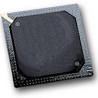
MPC564CZP40 Freescale Semiconductor, MPC564CZP40 Datasheet - Page 736

MPC564CZP40
Manufacturer Part Number
MPC564CZP40
Description
IC MPU 32BIT W/CODE COMP 388PBGA
Manufacturer
Freescale Semiconductor
Series
MPC5xxr
Specifications of MPC564CZP40
Core Processor
PowerPC
Core Size
32-Bit
Speed
40MHz
Connectivity
CAN, EBI/EMI, SCI, SPI, UART/USART
Peripherals
POR, PWM, WDT
Number Of I /o
56
Program Memory Size
512KB (512K x 8)
Program Memory Type
FLASH
Ram Size
32K x 8
Voltage - Supply (vcc/vdd)
2.5 V ~ 2.7 V
Data Converters
A/D 32x10b
Oscillator Type
External
Operating Temperature
-40°C ~ 85°C
Package / Case
388-BGA
Processor Series
MPC5xx
Core
PowerPC
Data Bus Width
32 bit
Data Ram Size
32 KB
Interface Type
CAN, JTAG, QSPI, SCI, SPI, UART
Maximum Clock Frequency
40 MHz
Number Of Programmable I/os
56
Number Of Timers
2
Operating Supply Voltage
0 V to 5 V
Maximum Operating Temperature
+ 85 C
Mounting Style
SMD/SMT
Minimum Operating Temperature
- 40 C
On-chip Adc
2 (10 bit, 32 Channel)
For Use With
MPC564EVB - KIT EVAL FOR MPC561/562/563/564
Lead Free Status / RoHS Status
Contains lead / RoHS non-compliant
Eeprom Size
-
Lead Free Status / Rohs Status
No
Available stocks
Company
Part Number
Manufacturer
Quantity
Price
Company:
Part Number:
MPC564CZP40
Manufacturer:
Freescale Semiconductor
Quantity:
10 000
- Current page: 736 of 1420
- Download datasheet (11Mb)
Modular Input/Output Subsystem (MIOS14)
17.2.1
A block is a group of four 16-bit registers. Each of the blocks within the MIOS14 addressing range is
assigned a block number. The first block is located at the base address of the MIOS14. The blocks are
numbered sequentially starting from 0.
17-4
•
•
— Possible use of signal as I/O port when MDASM function is not needed
MIOS14 pulse width modulation submodule (MPWMSM):
— Output pulse width modulated (PWM) signal generation with no software involvement
— Built-in 8-bit programmable prescaler clocked by the MCPSM
— PWM period and pulse width values provided by software:
— Programmable duty cycle from 0% to 100%
— Possible interrupt generation after every period
— Software selectable output pulse polarity
— Software readable output signal status
— Possible use of signal as I/O port when PWM function is not needed
MIOS14 16-bit parallel port I/O submodule (MPIOSM):
— Up to 16 parallel I/O signals per MPIOSM
— Uses four 16-bit registers in the address space, one for data and one for direction and two
— Simple data direction register (DDR) concept for selection of signal direction
– Double-buffered for glitch-free period and pulse width changes
– Two-cycle minimum output period/pulse-width increment
– 50% duty-cycle output maximum frequency: 10 MHz
– Up to 16 bits output pulse width resolution
– Wide range of periods:
– Wide range of frequencies:
reserved
Submodule Numbering, Naming, and Addressing
(50 ns @ 40 MHz)
•
•
•
•
•
•
16 bits of resolution: period range from 3.27 ms (with 50-ns steps) to
6.71 s (with 102.4 µs steps)
Eight bits of resolution: period range from 12.8 µs (with 50-ns steps) to
26.2 ms (with 102.4-µs steps)
Maximum output frequency at f
and divide-by-2 prescaler selection: 305 Hz (3.27 ms)
Minimum output frequency at f
and divide-by-4096 prescaler selection: 0.15 Hz (6.7 s)
Maximum output frequency at f
resolution and divide-by-2 prescaler selection: 78125 Hz (12.8 µs)
Minimum output frequency at f
and divide-by-4096 prescaler selection: 38.14 Hz (8.2 ms)
MPC561/MPC563 Reference Manual, Rev. 1.2
SYS
SYS
SYS
SYS
= 40 MHz with 16 bits of resolution
= 40 MHz with 16 bits of resolution
= 40 MHz with 8 bits of resolution
= 40 MHz with eight bits of
Freescale Semiconductor
Related parts for MPC564CZP40
Image
Part Number
Description
Manufacturer
Datasheet
Request
R

Part Number:
Description:
MPC5 1K0 5%
Manufacturer:
TE Connectivity
Datasheet:

Part Number:
Description:
MPC5 500R 5%
Manufacturer:
TE Connectivity
Datasheet:

Part Number:
Description:
MPC5 5K0 5%
Manufacturer:
Tyco Electronics
Datasheet:

Part Number:
Description:
MPC5 5R0 5%
Manufacturer:
Tyco Electronics
Datasheet:

Part Number:
Description:
MPC5 50K 5%
Manufacturer:
Tyco Electronics
Datasheet:

Part Number:
Description:
MPC5 1R0 5%
Manufacturer:
Tyco Electronics
Datasheet:
Part Number:
Description:
Manufacturer:
Freescale Semiconductor, Inc
Datasheet:
Part Number:
Description:
Manufacturer:
Freescale Semiconductor, Inc
Datasheet:
Part Number:
Description:
Manufacturer:
Freescale Semiconductor, Inc
Datasheet:
Part Number:
Description:
Manufacturer:
Freescale Semiconductor, Inc
Datasheet:
Part Number:
Description:
Manufacturer:
Freescale Semiconductor, Inc
Datasheet:


