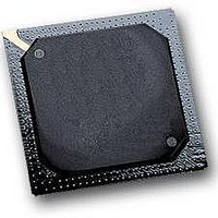
MPC564CZP40 Freescale Semiconductor, MPC564CZP40 Datasheet - Page 4

MPC564CZP40
Manufacturer Part Number
MPC564CZP40
Description
IC MPU 32BIT W/CODE COMP 388PBGA
Manufacturer
Freescale Semiconductor
Series
MPC5xxr
Specifications of MPC564CZP40
Core Processor
PowerPC
Core Size
32-Bit
Speed
40MHz
Connectivity
CAN, EBI/EMI, SCI, SPI, UART/USART
Peripherals
POR, PWM, WDT
Number Of I /o
56
Program Memory Size
512KB (512K x 8)
Program Memory Type
FLASH
Ram Size
32K x 8
Voltage - Supply (vcc/vdd)
2.5 V ~ 2.7 V
Data Converters
A/D 32x10b
Oscillator Type
External
Operating Temperature
-40°C ~ 85°C
Package / Case
388-BGA
Processor Series
MPC5xx
Core
PowerPC
Data Bus Width
32 bit
Data Ram Size
32 KB
Interface Type
CAN, JTAG, QSPI, SCI, SPI, UART
Maximum Clock Frequency
40 MHz
Number Of Programmable I/os
56
Number Of Timers
2
Operating Supply Voltage
0 V to 5 V
Maximum Operating Temperature
+ 85 C
Mounting Style
SMD/SMT
Minimum Operating Temperature
- 40 C
On-chip Adc
2 (10 bit, 32 Channel)
For Use With
MPC564EVB - KIT EVAL FOR MPC561/562/563/564
Lead Free Status / RoHS Status
Contains lead / RoHS non-compliant
Eeprom Size
-
Lead Free Status / Rohs Status
No
Available stocks
Company
Part Number
Manufacturer
Quantity
Price
Company:
Part Number:
MPC564CZP40
Manufacturer:
Freescale Semiconductor
Quantity:
10 000
- Current page: 4 of 1420
- Download datasheet (11Mb)
1.9
2.1
2.2
2.2.1
2.2.2
2.3
2.4
2.5
2.5.1
2.5.2
2.5.3
2.6
2.6.1
2.6.2
2.6.3
2.6.4
2.6.4.1
2.6.4.2
2.6.4.3
2.6.4.4
2.6.5
3.1
3.2
3.3
3.4
3.4.1
3.4.2
3.4.3
3.4.4
3.5
3.6
Freescale Semiconductor
Paragraph
Number
Supporting Documentation List .................................................................................... 1-14
Signal Groupings ............................................................................................................ 2-1
Signal Summary .............................................................................................................. 2-3
Pad Module Configuration Register (PDMCR) ............................................................ 2-22
Pad Module Configuration Register (PDMCR2) .......................................................... 2-23
MPC561/MPC563 Development Support Signal Sharing ............................................ 2-28
Reset State ..................................................................................................................... 2-31
RCPU Block Diagram .................................................................................................... 3-1
RCPU Key Features ........................................................................................................ 3-3
Instruction Sequencer ..................................................................................................... 3-3
Independent Execution Units .......................................................................................... 3-4
Levels of the PowerPC ISA Architecture ....................................................................... 3-6
RCPU Programming Model ............................................................................................ 3-7
MPC561/MPC563 Signal Multiplexing ................................................................... 2-20
READI Port Signal Sharing ...................................................................................... 2-21
JTAG Mode Selection .............................................................................................. 2-29
BDM Mode Selection ............................................................................................... 2-30
Nexus Mode Selection .............................................................................................. 2-30
Signal Functionality Configuration Out of Reset ..................................................... 2-31
Signal State During Reset ......................................................................................... 2-31
Power-On Reset and Hard Reset .............................................................................. 2-32
Pull-Up/Pull-Down ................................................................................................... 2-32
Signal Reset States .................................................................................................... 2-33
Branch Processing Unit (BPU) ................................................................................... 3-5
Integer Unit (IU) ......................................................................................................... 3-5
Load/Store Unit (LSU) ............................................................................................... 3-6
Floating-Point Unit (FPU) .......................................................................................... 3-6
Pull-Up/Pull-Down Enable and Disable for 5-V Only and 2.6-V Only Signals .. 2-32
Pull-Down Enable and Disable for 5-V/2.6-V Multiplexed Signals .................... 2-32
Special Pull Resistor Disable Control Functionality (SPRDS) ............................ 2-32
Pull Device Select (PULL_SEL) .......................................................................... 2-33
MPC561/MPC563 Reference Manual, Rev. 1.2
Central Processing Unit
Signal Descriptions
Contents
Chapter 2
Chapter 3
Title
Number
Page
iv
Related parts for MPC564CZP40
Image
Part Number
Description
Manufacturer
Datasheet
Request
R

Part Number:
Description:
MPC5 1K0 5%
Manufacturer:
TE Connectivity
Datasheet:

Part Number:
Description:
MPC5 500R 5%
Manufacturer:
TE Connectivity
Datasheet:

Part Number:
Description:
MPC5 5K0 5%
Manufacturer:
Tyco Electronics
Datasheet:

Part Number:
Description:
MPC5 5R0 5%
Manufacturer:
Tyco Electronics
Datasheet:

Part Number:
Description:
MPC5 50K 5%
Manufacturer:
Tyco Electronics
Datasheet:

Part Number:
Description:
MPC5 1R0 5%
Manufacturer:
Tyco Electronics
Datasheet:
Part Number:
Description:
Manufacturer:
Freescale Semiconductor, Inc
Datasheet:
Part Number:
Description:
Manufacturer:
Freescale Semiconductor, Inc
Datasheet:
Part Number:
Description:
Manufacturer:
Freescale Semiconductor, Inc
Datasheet:
Part Number:
Description:
Manufacturer:
Freescale Semiconductor, Inc
Datasheet:
Part Number:
Description:
Manufacturer:
Freescale Semiconductor, Inc
Datasheet:


