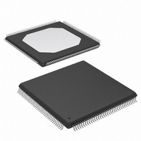
XCV50-6TQ144C Xilinx Inc, XCV50-6TQ144C Datasheet - Page 7

XCV50-6TQ144C
Manufacturer Part Number
XCV50-6TQ144C
Description
IC FPGA 2.5V C-TEMP 144-TQFP
Manufacturer
Xilinx Inc
Series
Virtex™r
Datasheet
1.XCV100-5PQ240C.pdf
(76 pages)
Specifications of XCV50-6TQ144C
Number Of Logic Elements/cells
1728
Number Of Labs/clbs
384
Total Ram Bits
32768
Number Of I /o
98
Number Of Gates
57906
Voltage - Supply
2.375 V ~ 2.625 V
Mounting Type
Surface Mount
Operating Temperature
0°C ~ 85°C
Package / Case
144-LQFP
Case
TQFP144
Dc
03+
Lead Free Status / RoHS Status
Contains lead / RoHS non-compliant
Available stocks
Company
Part Number
Manufacturer
Quantity
Price
Company:
Part Number:
XCV50-6TQ144C
Manufacturer:
XIL
Quantity:
1 238
Company:
Part Number:
XCV50-6TQ144C
Manufacturer:
XILINX
Quantity:
988
Input Path
A buffer In the Virtex IOB input path routes the input signal
either directly to internal logic or through an optional input
flip-flop.
An optional delay element at the D-input of this flip-flop elim-
inates pad-to-pad hold time. The delay is matched to the
internal clock-distribution delay of the FPGA, and when
used, assures that the pad-to-pad hold time is zero.
Each input buffer can be configured to conform to any of the
low-voltage signalling standards supported. In some of
these standards the input buffer utilizes a user-supplied
threshold voltage, V
constraints on which standards can used in close proximity
to each other. See I/O
There are optional pull-up and pull-down resistors at each
user I/O input for use after configuration. Their value is in
the range 50 kΩ – 100 kΩ.
Output Path
The output path includes a 3-state output buffer that drives
the output signal onto the pad. The output signal can be
routed to the buffer directly from the internal logic or through
an optional IOB output flip-flop.
The 3-state control of the output can also be routed directly
from the internal logic or through a flip-flip that provides syn-
chronous enable and disable.
Each output driver can be individually programmed for a
wide range of low-voltage signalling standards. Each output
buffer can source up to 24 mA and sink up to 48mA. Drive
strength and slew rate controls minimize bus transients.
In most signalling standards, the output High voltage
depends on an externally supplied V
to supply V
can be used in close proximity to each other. See I/O Bank-
ing, page
An optional weak-keeper circuit is connected to each out-
put. When selected, the circuit monitors the voltage on the
pad and weakly drives the pin High or Low to match the
input signal. If the pin is connected to a multiple-source sig-
nal, the weak keeper holds the signal in its last state if all
drivers are disabled. Maintaining a valid logic level in this
way eliminates bus chatter.
Because the weak-keeper circuit uses the IOB input buffer
to monitor the input level, an appropriate V
be provided if the signalling standard requires one. The pro-
vision of this voltage must comply with the I/O banking
rules.
I/O Banking
Some of the I/O standards described above require V
and/or V
nected to device pins that serve groups of IOBs, called
banks. Consequently, restrictions exist about which I/O
standards can be combined within a given bank.
DS003-2 (v2.8.1) December 9, 2002
Product Specification
REF
3.
CCO
R
voltages. These voltages externally and con-
imposes constraints on which standards
REF
Banking, page
. The need to supply V
CCO
3.
voltage. The need
REF
REF
voltage must
imposes
www.xilinx.com
1-800-255-7778
CCO
Eight I/O banks result from separating each edge of the
FPGA into two banks, as shown in
multiple V
same voltage. This voltage is determined by the output
standards in use.
Within a bank, output standards can be mixed only if they
use the same V
Table
their open-drain outputs do not depend on V
Table 2: Compatible Output Standards
Some input standards require a user-supplied threshold
voltage, V
matically configured as inputs for the V
imately one in six of the I/O pins in the bank assume this
role.
The V
and consequently only one V
each bank. All V
nected to the external voltage source for correct operation.
Within a bank, inputs that require V
those that do not. However, only one V
used within a bank. Input buffers that use V
tolerant. LVTTL, LVCMOS2, and PCI 33 MHz 5 V, are 5 V
tolerant.
The V
Pinout tables and diagrams. The diagrams also show the
bank affiliation of each I/O.
Within a given package, the number of V
can vary depending on the size of device. In larger devices,
3.3 V
2.5 V
1.5 V
V
CCO
2. GTL and GTL+ appear under all voltages because
CCO
REF
Virtex™ 2.5 V Field Programmable Gate Arrays
PCI, LVTTL, SSTL3 I, SSTL3 II, CTT, AGP, GTL,
GTL+
SSTL2 I, SSTL2 II, LVCMOS2, GTL, GTL+
HSTL I, HSTL III, HSTL IV, GTL, GTL+
CCO
REF
and V
pins within a bank are interconnected internally
. In this case, certain user-I/O pins are auto-
pins, all of which must be connected to the
REF
REF
CCO
Figure 3:
Bank 0
Bank 5
pins in the bank, however, must be con-
pins for each bank appear in the device
. Compatible standards are shown in
Compatible Standards
GCLK3 GCLK2
GCLK1 GCLK0
Device
Virtex
Virtex I/O Banks
REF
voltage can be used within
Bank 1
Bank 4
Figure
REF
REF
REF
REF
X8778_b
can be mixed with
3. Each bank has
voltage. Approx-
REF
voltage can be
CCO
and V
Module 2 of 4
are not 5 V
.
CCO
pins
3


