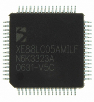
XE8805AMI028LF Semtech, XE8805AMI028LF Datasheet - Page 118

XE8805AMI028LF
Manufacturer Part Number
XE8805AMI028LF
Description
IC DAS 16BIT FLASH 8K MTP 64LQFP
Manufacturer
Semtech
Datasheet
1.XE8805AMI028LF.pdf
(156 pages)
Specifications of XE8805AMI028LF
Applications
Sensing Machine
Core Processor
RISC
Program Memory Type
FLASH (22 kB)
Controller Series
XE8000
Ram Size
512 x 8
Interface
UART, USRT
Number Of I /o
24
Voltage - Supply
2.4 V ~ 5.5 V
Operating Temperature
-40°C ~ 85°C
Mounting Type
Surface Mount
Package / Case
64-LQFP
Supply Voltage Range
2.4V To 5.5V
Operating Temperature Range
-40°C To +85°C
Digital Ic Case Style
LQFP
No. Of Pins
64
For Use With
XE8000MP - PROG BOARD AND PROSTART2 CARD
Lead Free Status / RoHS Status
Lead free / RoHS Compliant
Available stocks
Company
Part Number
Manufacturer
Quantity
Price
Part Number:
XE8805AMI028LF
Manufacturer:
SEMTECH/美国升特
Quantity:
20 000
16.9.4
The incremental ADC is an over-sampled converter with two main blocks: an analog modulator and a low-pass
digital filter. The main function of the digital filter is to remove the quantization noise introduced by the modulator.
As shown in Figure 16-26, this filter determines the frequency response of the transfer function between the output
of the ADC and the analog input V
period OSR/f
elementary conversions N
and are repeated every f
Information on the location of these notches is particularly useful when specific frequencies must be filtered out by
the acquisition system. For example, consider a 5Hz-bandwidth, 16-bit sensing system where 50Hz line rejection is
needed. Using the above equation and the plots below, we set the 4th notch for N
1.25⋅f
choice yields also good attenuation of 50Hz harmonics.
© Semtech 2006
1.2
0.8
0.6
0.4
0.2
1.2
0.8
0.6
0.4
0.2
4)
5)
6)
1
0
S
1
0
/OSR = 50Hz. The sampling frequency is then calculated as f
0
0
f
For highest linearity and lowest noise performance, bypass all PGAs and use the ADC alone (applications
where no "zooming" is needed); i.e. set ENABLE[3:0] = '0001'.
For low-noise applications where power consumption is not a primary concern, maintain the largest bias
currents in the PGAs and in the ADC; i.e. set IB_AMP_PGA[1:0] = IB_AMP_ADC[1:0] = '11'.
For lowest output offset error at the output of the ADC, bypass PGA2 and PGA3. Indeed, PGA2 and
PGA3 typically introduce an offset of about 5 to 10 LSB (16 bit) at their output. Note, however, that the
ADC output offset is easily calibrated out by software.
NOTCH
Frequency Response
Figure 16-26. Frequency response: normalized magnitude vs. frequency for different N
S
. The plots of Figure 16-26 also show that the frequency response changes with the number of
Normalized Frequency - f *(OSR/f
) (
Normalized Frequency - f *(OSR/f
i
1
1
=
OSR
i
⋅
S
⋅
N
/OSR.
ELCONV
f
ELCONV
2
S
2
performed. In particular, notches appear for N
IN
N
N
ELCONV
. Notice that the frequency axes are normalized to one elementary conversion
ELCONV
3
S
3
S
) [-]
) [-]
(Hz)
= 1
= 4
4
4
for
i
=
1
16-32
2 ,
1.2
0.8
0.6
0.4
0.2
1.2
0.8
0.6
0.4
0.2
,...,
1
0
1
0
0
0
(
N
ELCONV
Normalized Frequency - f *(OSR/f
Normalized Frequency - f *(OSR/f
1
−
1
S
) 1
= 20.48kHz for OSR = 512. Notice that this
ELCONV
2
2
(Eq. 23)
≥ 2. These notches occur at:
N
N
ELCONV
ELCONV
3
3
S
S
) [-]
ELCONV
) [-]
= 2
= 8
XE8805/05A
= 4 to 50Hz, i.e.
4
4
www.semtech.com
ELCONV


