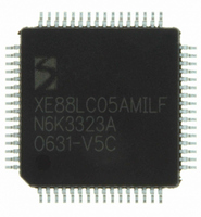
XE8805AMI028LF Semtech, XE8805AMI028LF Datasheet - Page 92

XE8805AMI028LF
Manufacturer Part Number
XE8805AMI028LF
Description
IC DAS 16BIT FLASH 8K MTP 64LQFP
Manufacturer
Semtech
Datasheet
1.XE8805AMI028LF.pdf
(156 pages)
Specifications of XE8805AMI028LF
Applications
Sensing Machine
Core Processor
RISC
Program Memory Type
FLASH (22 kB)
Controller Series
XE8000
Ram Size
512 x 8
Interface
UART, USRT
Number Of I /o
24
Voltage - Supply
2.4 V ~ 5.5 V
Operating Temperature
-40°C ~ 85°C
Mounting Type
Surface Mount
Package / Case
64-LQFP
Supply Voltage Range
2.4V To 5.5V
Operating Temperature Range
-40°C To +85°C
Digital Ic Case Style
LQFP
No. Of Pins
64
For Use With
XE8000MP - PROG BOARD AND PROSTART2 CARD
Lead Free Status / RoHS Status
Lead free / RoHS Compliant
Available stocks
Company
Part Number
Manufacturer
Quantity
Price
Part Number:
XE8805AMI028LF
Manufacturer:
SEMTECH/美国升特
Quantity:
20 000
16.4.2
Figure 16-2 shows a detailed functional diagram of the ZoomingADC™.
In table 16-10 the configuration of the peripheral registers is detailed. The system has a bank of eight 8-bit
registers: six registers are used to configure the acquisition chain (RegAcCfg0 to 5), and two registers are used
to store the output code of the analog-to-digital conversion (RegAcOutMsb & Lsb). The register coding of the
ADC parameters and performance characteristics are detailed in Section 16.7.
With:
•
•
•
•
•
•
•
•
•
•
•
•
•
•
•
© Semtech 2006
OUT: (r) digital output code of the analog-to-digital converter. (MSB = OUT[15])
START: (w) setting this bit triggers a single conversion (after the current one is finished). This bit always reads back 0.
SET_NELC: (rw) sets the number of elementary conversions to 2
is chopped between elementary conversions (1,2,4,8).
SET_OSR: (rw) sets the over-sampling rate (OSR) of an elementary conversion to 2
512, 1024.
CONT: (rw) setting this bit starts a conversion. A new conversion will automatically begin as long as the bit remains at 1.
TEST: bit only used for test purposes. In normal mode, this bit is forced to 0 and cannot be overwritten.
IB_AMP_ADC: (rw) sets the bias current in the ADC to 0.25*(1+ IB_AMP_ADC[1:0]) of the normal operation current (25,
50, 75 or 100% of nominal current). To be used for low-power, low-speed operation.
IB_AMP_PGA: (rw) sets the bias current in the PGAs to 0.25*(1+IB_AMP_PGA[1:0]) of the normal operation current (25,
50, 75 or 100% of nominal current). To be used for low-power, low-speed operation.
ENABLE: (rw) enables the ADC modulator (bit 0) and the different stages of the PGAs (PGAi by bit i=1,2,3). PGA stages
that are disabled are bypassed.
FIN: (rw) These bits set the sampling frequency of the acquisition chain. Expressed as a fraction of the oscillator frequency,
the sampling frequency is given as: 00
PGA1_GAIN: (rw) sets the gain of the first stage: 0
PGA2_GAIN: (rw) sets the gain of the second stage: 00
PGA3_GAIN: (rw) sets the gain of the third stage to PGA3_GAIN[6:0]⋅1/12.
PGA2_OFFSET: (rw) sets the offset of the second stage between –1 and +1, with increments of 0.2. The MSB gives the sign
(0 → positive, 1 → negative); amplitude is coded with the bits PGA2_OFFSET[5:0].
PGA3_OFFSET: (rw) sets the offset of the third stage between –5.25 and +5.25, with increments of 1/12. The MSB gives the
sign (0 → positive, 1 → negative); amplitude is coded with the bits PGA3_OFFSET[5:0].
Default values:
Default values:
Default values:
Default values:
Default values:
Default values:
RegAcOutLsb
RegAcOutMsb
RegAcCfg0
RegAcCfg1
RegAcCfg2
RegAcCfg3
RegAcCfg4
RegAcCfg5
Register
Name
Peripheral Registers
Table 16-10. Peripheral registers to configure the acquisition chain (AC)
IB_AMP_ADC[1:0]
PGA1_G
START
BUSY
7
0
0
0
0
FIN[1:0]
and to store the analog-to-digital conversion (ADC) result
11
00
SET_NELC[1:0]
DEF
0
6
01
1/4 f
PGA2_GAIN[1:0]
IB_AMP_PGA[1:0]
5
RC
, 01
11
00
1, 1
1/8 f
Bit Position
OUT[15:8]
4
16-6
OUT[7:0]
PGA3_OFFSET[6:0]
1, 01
PGA3_GAIN[6:0]
RC
SET_OSR[2:0]
10.
AMUX[4:0]
, 10
0000000
0000000
00000
SET_NELC[1:0]
010
2, 10
3
1/32 f
PGA2_OFFSET[3:0]
RC
5, 11
ENABLE[3:0]
, 11
2
. To compensate for offsets, the input signal
0001
0000
10.
~8kHz.
(3+SET_OSR[2:0])
CONT
1
0
TEST
VMUX
XE8805/05A
0
0
0
. OSR = 8, 16, 32, ...,
www.semtech.com


