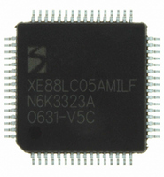
XE8805AMI028LF Semtech, XE8805AMI028LF Datasheet - Page 138

XE8805AMI028LF
Manufacturer Part Number
XE8805AMI028LF
Description
IC DAS 16BIT FLASH 8K MTP 64LQFP
Manufacturer
Semtech
Datasheet
1.XE8805AMI028LF.pdf
(156 pages)
Specifications of XE8805AMI028LF
Applications
Sensing Machine
Core Processor
RISC
Program Memory Type
FLASH (22 kB)
Controller Series
XE8000
Ram Size
512 x 8
Interface
UART, USRT
Number Of I /o
24
Voltage - Supply
2.4 V ~ 5.5 V
Operating Temperature
-40°C ~ 85°C
Mounting Type
Surface Mount
Package / Case
64-LQFP
Supply Voltage Range
2.4V To 5.5V
Operating Temperature Range
-40°C To +85°C
Digital Ic Case Style
LQFP
No. Of Pins
64
For Use With
XE8000MP - PROG BOARD AND PROSTART2 CARD
Lead Free Status / RoHS Status
Lead free / RoHS Compliant
Available stocks
Company
Part Number
Manufacturer
Quantity
Price
Part Number:
XE8805AMI028LF
Manufacturer:
SEMTECH/美国升特
Quantity:
20 000
19.6 Application examples
19.6.1
Figure 19-2 shows the basic connectivity to have a voltage controlled sensor bias. The D/A will generate a voltage
between vrep and vrefn proportional to the input code. The amplifier will copy the D/A voltage to the sensor. The
D/A code can be used to do a software temperature calibration of the sensor for instance.
Filter capacitors can be added in parallel with the sensor reference and signal, on V
The voltages V
voltages can be connected directly to VBAT and VSS for simplicity. They can also be connected to VBAT and VSS
through a low pass filter that rejects the high frequency supply noise. Finally, in most cases, the voltage range of
interest for the voltage V
equal to the limits of the voltage range of interest, the resolution of the D/A can be increased. Example: if a supply
of 5V is used and the reference voltage is equal to the supply, the D/A can generate a sensor voltage between 0V
and 5V in steps of about 5V/255≈20mV. If the sensor voltage is always to be between 3V and 4V, and by
connecting V
1V/255≈4mV.
Note that the voltage on the sensor can not be higher than VBAT-0.2V in the example of Figure 19-2 (specification
VR
19.6.2
Figure 19-3 shows the principle of a current controlled sensor bias schematic. In this case, the amplifier forces the
voltage V
© Semtech 2006
AOM
in Table 19-4).
XE8805A – DAB block
R
Voltage controlled sensor bias
Current controlled sensor bias
to be equal to the D/A output voltage V
In this configuration the bridge current and DAB_AOM
refn
refp
=3V and V
and V
D/A
sensor
increase when DAB_OUT increases.
refn
refp
can be filtered before being connected to the D/A reference inputs. The reference
=4V, the sensor voltage is adjustable between 3V and 4V with steps of about
on the sensor is only a fraction of the supply voltage. By generating V
Figure 19-2. Voltage controlled bridge bias principle.
amp
DAB_AOM
DAB_R_M
DAB_OUT
DAB_AOP
D/A
DAB_R_P
DAB_AIM
DAB_AIP
. The current I
19-4
V
V
refp
refn
VBAT
sensor
VBAT or a Reference voltage source
VSS
V
sensor
through the sensor is given by:
VSS
impedance depends on D/A code
High impedance node,
Needs a 300
Max capacitive load is 1 nF
refp
, V
refn
reference input
of the
ZoomingADC
Ω
– 100 k
and DAB_OUT.
signal input
of the
ZoomingADC
XE8805/05A
Ω
load
www.semtech.com
refp
and V
refn


