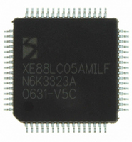
XE8805AMI028LF Semtech, XE8805AMI028LF Datasheet - Page 147

XE8805AMI028LF
Manufacturer Part Number
XE8805AMI028LF
Description
IC DAS 16BIT FLASH 8K MTP 64LQFP
Manufacturer
Semtech
Datasheet
1.XE8805AMI028LF.pdf
(156 pages)
Specifications of XE8805AMI028LF
Applications
Sensing Machine
Core Processor
RISC
Program Memory Type
FLASH (22 kB)
Controller Series
XE8000
Ram Size
512 x 8
Interface
UART, USRT
Number Of I /o
24
Voltage - Supply
2.4 V ~ 5.5 V
Operating Temperature
-40°C ~ 85°C
Mounting Type
Surface Mount
Package / Case
64-LQFP
Supply Voltage Range
2.4V To 5.5V
Operating Temperature Range
-40°C To +85°C
Digital Ic Case Style
LQFP
No. Of Pins
64
For Use With
XE8000MP - PROG BOARD AND PROSTART2 CARD
Lead Free Status / RoHS Status
Lead free / RoHS Compliant
Available stocks
Company
Part Number
Manufacturer
Quantity
Price
Part Number:
XE8805AMI028LF
Manufacturer:
SEMTECH/美国升特
Quantity:
20 000
When in upcount mode, the counter will start incrementing from zero up to the target value which has been written
in the corresponding RegCntX register(s). When the counter content is equal to the target value, an interrupt is
generated at the next falling edge of counter clock. Then the counter is loaded again with the zero value at the next
rising edge of counter clock (Figure 20-2).
When in downcount mode, the counter will start decrementing from the initial load value which has been written in
the corresponding RegCntX register(s) down to the zero value. Once the counter content is equal to zero, an
interrupt is generated at the next falling edge of counter clock. Then the counter is loaded again with the load value
at the next rising edge of counter clock (Figure 20-2).
Be careful to select the counter mode (no capture, not PWM, specify cascaded or not and up or down counting
mode) before writing any target or load value to the RegCntX register(s). This ensures that the counter will start
from the correct initial value. When counters are cascaded, both counter registers must be written to ensure that
both cascaded counters will start from the correct initial values.
The stopping and consecutive starting of a counter in counter mode without a target or load value write operation in
between can generate an interrupt if this counter has been stopped at the zero value (downcount) or at it’s target
value (upcount). This interrupt is additional to the interrupt which has already been generated when the counter
reached the zero or the target value.
© Semtech 2006
dow n counting
up counting
clock counter X
clock counter X
write RegCntX
write RegCntX
CntXDownUp
CntXDownUp
CntXEnable
CntXEnable
RegCntX_w
RegCntX_w
RegCntX_r
RegcntX_r
IrqX
IrqX
XX
XX
XX
XX
Figure 20-2. Up and down count interrupt generation.
0
3
3
1
2
3
2
1
3
0
20-7
0
3
1
2
2
1
3
0
0
3
1
2
2
XE8805/05A
1
3
www.semtech.com
0


