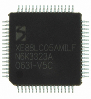
XE8805AMI028LF Semtech, XE8805AMI028LF Datasheet - Page 139

XE8805AMI028LF
Manufacturer Part Number
XE8805AMI028LF
Description
IC DAS 16BIT FLASH 8K MTP 64LQFP
Manufacturer
Semtech
Datasheet
1.XE8805AMI028LF.pdf
(156 pages)
Specifications of XE8805AMI028LF
Applications
Sensing Machine
Core Processor
RISC
Program Memory Type
FLASH (22 kB)
Controller Series
XE8000
Ram Size
512 x 8
Interface
UART, USRT
Number Of I /o
24
Voltage - Supply
2.4 V ~ 5.5 V
Operating Temperature
-40°C ~ 85°C
Mounting Type
Surface Mount
Package / Case
64-LQFP
Supply Voltage Range
2.4V To 5.5V
Operating Temperature Range
-40°C To +85°C
Digital Ic Case Style
LQFP
No. Of Pins
64
For Use With
XE8000MP - PROG BOARD AND PROSTART2 CARD
Lead Free Status / RoHS Status
Lead free / RoHS Compliant
Available stocks
Company
Part Number
Manufacturer
Quantity
Price
Part Number:
XE8805AMI028LF
Manufacturer:
SEMTECH/美国升特
Quantity:
20 000
The voltage V
Note that the voltage V
guarantee correct functionality of this schematic.
Choosing the V
voltage on the sensor is recommended. From the equation, it can be seen that the sensor current step per LSB can
be made smaller by reducing the voltage between V
As for the voltage controlled sensor bias, capacitors can be added on several nodes to filter out the noise.
In Figure 19-4, the sense resistor is inserted between the negative reference voltage and the sensor. This
schematic has the same principle as above, but it is easier to respect the limits on VR
sensor current is now:
In this case, it is recommended to choose V
voltage on the sensor. The only limit is now V
© Semtech 2006
XE8805A
I
I
sensor
sensor
sensor
In this configuration, the bridge current and DAB_AOM
=
=
D
refp
V
V
refp
R
can be calculated as a function of the current I
equal to the supply voltage or close to the supply voltage in order to have the highest possible
R
R
−
sense
sense
−
V
V
refn
R
R
>VSS+2.3V and V
A
decrease when DAB_OUT increases.
=
=
V
V
refp
D
/
R
R
A
−
sense
sense
Figure 19-3. Current controlled bridge bias
−
V
V
D
refn
/
A
amp
=
=
refn
sensor
(
(
R
V
V
-V
equal to VSS or close to VSS in order to have the highest possible
refp
refp
sensor
<VBAT-0.2V.
−
−
refp
DAB_AOM
DAB_OUT
DAB_R_M
DAB_AOP
DAB_R_P
V
V
DAB_AIM
>0.2V (VR
DAB_AIP
and V
refn
refn
19-5
R
)
)
R
sense
⋅
⋅
sense
1 (
(
refn
code
−
or by increasing the sense resistor value.
V
V
V
AOP
code
sensor
D/A
refp
refn
255
and VR
and the sensor impedance.
VSS
255
)
)
AOM
R
V
V
sense
R
sensor
VSS
specifications in Table 19-4) to
Voltage must remain above VSS + 2.3 V
Voltage must remain below VBAT - 2.3 V
Voltage must remain above VSS + 2.3 V
Needs a 300
Max capacitive load is 1 nF
AOP
when VBAT is low. The
reference
XE8805/05A
signal
Ω
– 100 k
www.semtech.com
Ω
load


