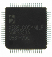
XE8805AMI028LF Semtech, XE8805AMI028LF Datasheet - Page 146

XE8805AMI028LF
Manufacturer Part Number
XE8805AMI028LF
Description
IC DAS 16BIT FLASH 8K MTP 64LQFP
Manufacturer
Semtech
Datasheet
1.XE8805AMI028LF.pdf
(156 pages)
Specifications of XE8805AMI028LF
Applications
Sensing Machine
Core Processor
RISC
Program Memory Type
FLASH (22 kB)
Controller Series
XE8000
Ram Size
512 x 8
Interface
UART, USRT
Number Of I /o
24
Voltage - Supply
2.4 V ~ 5.5 V
Operating Temperature
-40°C ~ 85°C
Mounting Type
Surface Mount
Package / Case
64-LQFP
Supply Voltage Range
2.4V To 5.5V
Operating Temperature Range
-40°C To +85°C
Digital Ic Case Style
LQFP
No. Of Pins
64
For Use With
XE8000MP - PROG BOARD AND PROSTART2 CARD
Lead Free Status / RoHS Status
Lead free / RoHS Compliant
Available stocks
Company
Part Number
Manufacturer
Quantity
Price
Part Number:
XE8805AMI028LF
Manufacturer:
SEMTECH/美国升特
Quantity:
20 000
Table 20-12 shows the different operation modes of the counters C and D as a function of the mode control bits.
For all counter modes, the source of the down or upcount selection is given (either the bit CntCDownUp or the bit
CntDDownUp). The mapping of the interrupt sources IrqC and IrqD and the PWM output on PB(1) in these
different modes is also shown.
The switching between different modes must be done while the concerned counters are stopped. While switching
capture mode on and off, unwanted interrupts can appear on the interrupt channels concerned by this mode
change.
20.9 Counter / Timer mode
The counters in counter / timer mode are generally used to generate interrupts after a predefined number of clock
periods applied on the counter clock input.
Each counter can be set individually either in upcount mode by setting CntXDownUp in the register
RegCntConfig1 or in downcount mode by resetting this bit. Counters A and B can be cascaded to behave as a 16
bit counter by setting CascadeAB in the RegCntConfig1 register. Counters C and D can be cascaded by setting
CascadeCD. When cascaded, the up/down count modes of the counters B and D are defined respectively by the
up/down count modes set for the counters A and C.
© Semtech 2006
CascadeCD
CascadeAB
0
1
0
1
0
1
0
0
1
0
1
CountPWM0
0
0
1
1
0
0
1
CapFunc(1:0)
CountPWM1
Table 20-11: Operating modes of the counters A and B
Table 20-12: Operating modes of the counters C and D
0
0
1
1
00
00
00
00
1x
x1
1x
x1
1x
x1
or
or
or
Counter 8b
Captured counter 16b AB
Counter A
Downup: A
Downup: A
counter 8b
Counter C
Counter 8b
Downup: C
Captured
PWM 8b
PWM 8b
PWM 8b
mode
Down
Down
mode
Down
PWM 10 – 16b AB
PWM 10 – 16b CD
Counter 16b AB
Counter 16b CD
Downup: A
Downup: A
Downup: C
Down
Down
20-6
Counter 8b
Counter 8b
Counter B
Downup: B
Downup: B
Downup: B
counter 8b
counter 8b
Captured
Captured
Counter 8b
Downup: D
Counter 8b
Counter D
mode
Down
mode
Down
Must not
Counter
Counter
Capture
Capture
be used
source
Counter
Counter
Source
IrqA
AB
AB
A
A
IrqC
-
-
CD
C
-
-
Counter
Counter
Capture
Capture
Capture
source
Counter
Counter
source
IrqB
AB
IrqD
B
B
B
B
-
-
D
D
-
-
PWM AB
function
XE8805/05A
PWM CD
PWM A
PWM A
function
PWM C
PB(0)
PB(0)
PB(0)
PB(0)
PB(0)
PB(1)
PB(1)
PB(1)
www.semtech.com


