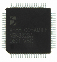
XE8805AMI028LF Semtech, XE8805AMI028LF Datasheet - Page 126

XE8805AMI028LF
Manufacturer Part Number
XE8805AMI028LF
Description
IC DAS 16BIT FLASH 8K MTP 64LQFP
Manufacturer
Semtech
Datasheet
1.XE8805AMI028LF.pdf
(156 pages)
Specifications of XE8805AMI028LF
Applications
Sensing Machine
Core Processor
RISC
Program Memory Type
FLASH (22 kB)
Controller Series
XE8000
Ram Size
512 x 8
Interface
UART, USRT
Number Of I /o
24
Voltage - Supply
2.4 V ~ 5.5 V
Operating Temperature
-40°C ~ 85°C
Mounting Type
Surface Mount
Package / Case
64-LQFP
Supply Voltage Range
2.4V To 5.5V
Operating Temperature Range
-40°C To +85°C
Digital Ic Case Style
LQFP
No. Of Pins
64
For Use With
XE8000MP - PROG BOARD AND PROSTART2 CARD
Lead Free Status / RoHS Status
Lead free / RoHS Compliant
Available stocks
Company
Part Number
Manufacturer
Quantity
Price
Part Number:
XE8805AMI028LF
Manufacturer:
SEMTECH/美国升特
Quantity:
20 000
increase the output signal bandwidth or to reduce the PWM switching frequency and therefore the power
consumption of the D/A. Signal distortion is less dependent on the signal value.
Disadvantages:
Using a high order noise shaper together with a PWM modulator with low resolution will use lots of short pulses in
stead of 1 long pulse. The D/A is therefore more sensitive to rise and fall times of the PWM resulting in a slightly
higher non-linearity and temperature dependence. The second order noise shaper also has a reduced resolution
for codes very close to zero or full scale.
18.4.3
In this section, the resolution that can be obtained with the D/A as a function of settings is calculated. These
calculations are based on the quantization and PWM modulation noise. Noise on the reference, i.e. the supply
voltage is not taken into account. High frequency noise on the supply voltage can be filtered by the output low pass
filter, but in band noise on the reference will show up in the output signal with amplitude that will depend on the
signal value. Therefore, when using the D/A, one should take care to minimize the switching activity on the digital
ports and/or to limit the load on these ports.
18.4.3.1
Setting the noise shaper to order 0 (NsOrder=00), reduces the D/A to a regular PWM. Two parameters are setting
the resolution of the D/A: the resolution of the modulator itself and the amount of low pass filtering at the output.
The modulation width
The cut-off frequency
modulator repetition frequency
frequency of the RC oscillator of the circuit
To obtain an analog signal with the required solution, the PWM signal has to be low pass filtered. The resolution
that can be obtained depends on the filter order and the ratio between the PWM modulation frequency
the filter cut-off frequency
The total resolution of the D/A is then the minimal value of both criteria:
In Table 18-5 the required cut-off frequency of the low pass filter is shown for a noise shaper of order 0 as a
function of the desired resolution for both a first and second order low pass filter. The PWM modulation factor m
should be chosen equal to the desired resolution.
© Semtech 2006
m
resolution
resolution =
f
PWM
D/A setup and resolution
Noise shaper of order 0
= 4
=
+
CodeLmax
f
RC
PWM
⋅
min(
m
⎛
⎜
⎝
2
1
f
=
m
c
of the PWM modulator is given by:
+
LpOrder
f
1
Fin
m
of the low pass filter required to get the resolution is calculated below. The PWM
c
. For a low pass filter of LpOrder, we obtain:
,
resolution
⎞
⎟
⎠
f
PWM
⋅
log
can be calculated as a function of the selected modulation width
2
PWM
⎛
⎜ ⎜
⎝
f
f
RC
PWM
)
f
c
and the selected frequency division set by Fin :
⎞
⎟ ⎟
⎠
18-5
XE8805/05A
www.semtech.com
f
PWM
m
, the
and


